5-10
PERFORMANCE DATA & PRESSURE CURVES
Revision 0
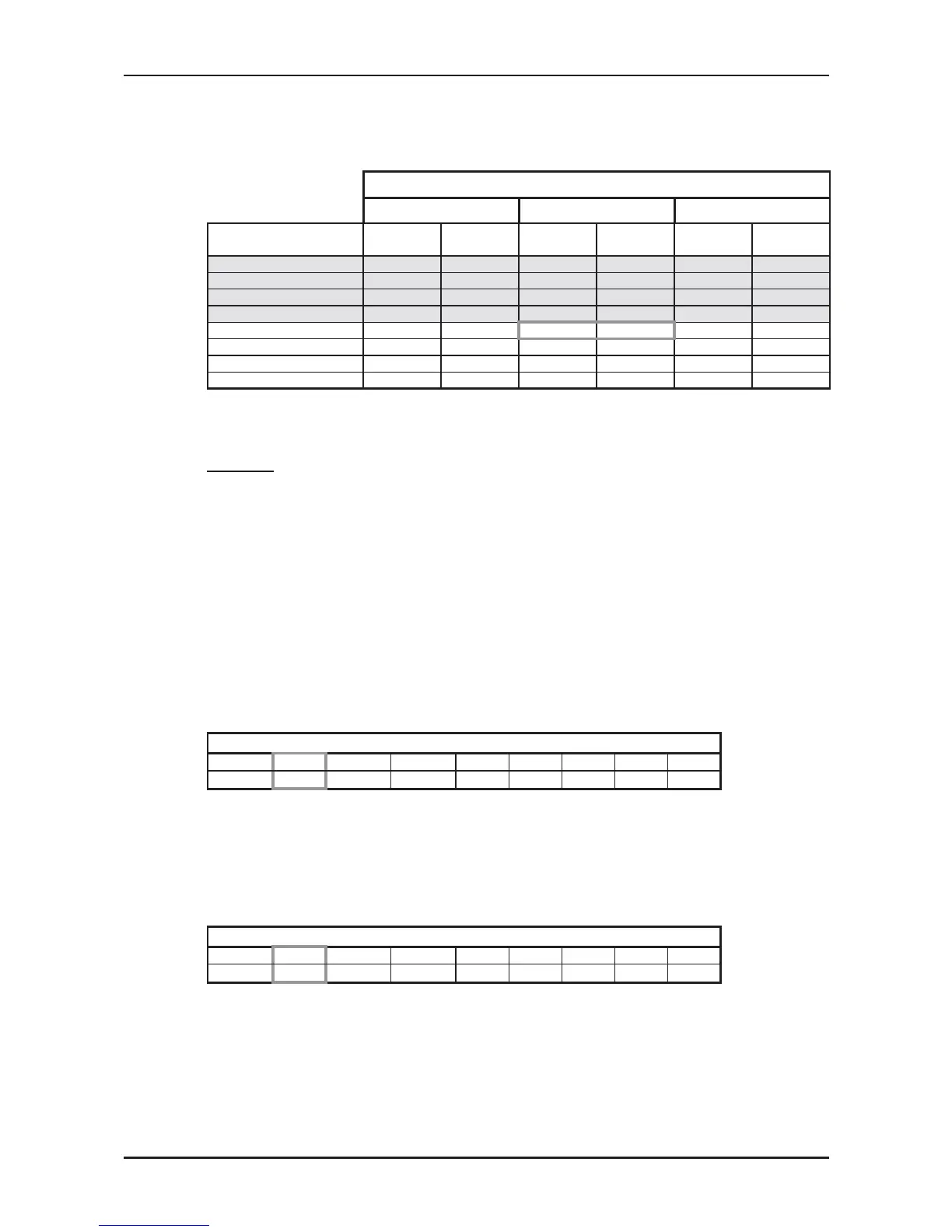
5.7.2 Heating Mode at 7.5m Tubing Connection.
230V : Indoor Fan at High Speed.
ENTERING AIR DB ID COIL ( °C)
15 20 25
ENTERING AIR WB
OU COIL (°C)
TH PI TH PI TH PI
-10 2.10 0.91 2.02 0.97 1.94 1.02
-7 2.26 0.93 2.18 0.99 2.10 1.04
-2 2.40 0.95 2.32 1.00 2.24 1.06
2 2.92 0.99
2.80 1.05
2.68 1.12
6 4.12 1.07 4.00 1.14 3.86 1.21
10 4.48 1.13
5.00 1.20
4.24 1.29
15 4.84 1.17 4.72 1.27 4.60 1.35
20 5.10 1.21 4.98 1.31 4.84 1.41
* the above chart includes the weighted deicing infleuence.
LEGEND
TH – Total Heating Capacity, kW
PI – Power Input, kW
WB – Wet Bulb Temp., (
o
C)
DB – Dry Bulb Temp., (
o
C)
ID – Indoor
OU – Outdoor
5.8 Capacity Correction Factor Due to Tubing Length
5.8.1 Cooling
TOTAL TUBING LENGTH (One Way)
3m
7.5m
10m 15m 20m 25m 30m 40m 50m
1.02
1
0.961 0.948 --- --- --- --- ---
* Minimum recommended tubing length between indoor and outdoor units is 3m.
5.8.2 Heating
TOTAL TUBING LENGTH (One Way)
3m
7.5m
10m 15m 20m 25m 30m 40m 50m
1.05
1
0.975 0.963 --- --- --- --- ---
* Minimum recommended tubing length between indoor and outdoor units is 3m.
 Loading...