5-14
PERFORMANCE DATA & PRESSURE CURVES
Revision 0
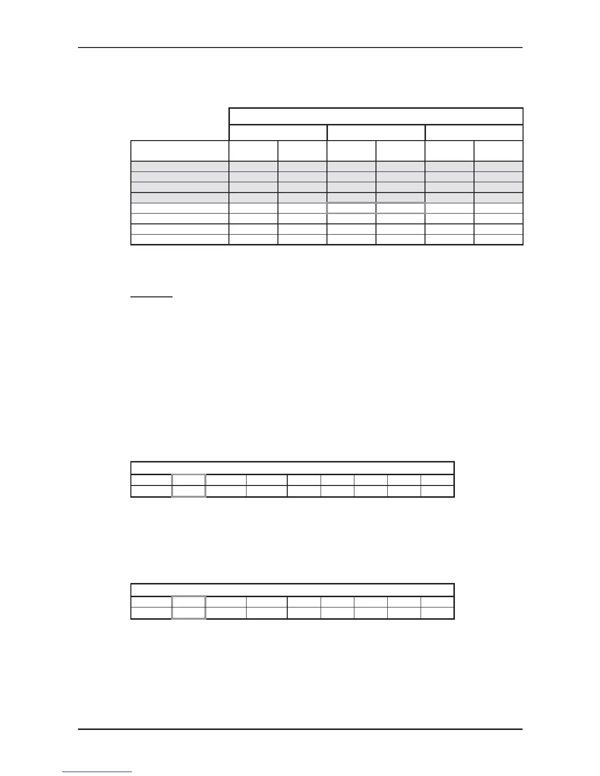
5.10.2 Heating Mode at 7.5m Tubing Connection.
230V : Indoor Fan at High Speed.
ENTERING AIR DB ID COIL ( °C)
15 20 25
ENTERING AIR WB
OU COIL (°C)
TH PI TH PI TH PI
-10 2.35 1.12 2.26 1.19 2.17 1.25
-7 2.53 1.15 2.44 1.21 2.35 1.28
-2 2.69 1.16 2.60 1.23 2.51 1.30
2 3.27 1.22
3.14 1.30
3.00 1.37
6 4.61 1.31 4.48 1.40 4.32 1.49
10 5.02 1.38
4.88 1.48
4.75 1.58
15 5.42 1.44 5.29 1.55 5.15 1.65
20 5.71 1.48 5.58 1.61 5.42 1.74
* the above chart includes the weighted deicing infleuence.
LEGEND
TH – Total Heating Capacity, kW
PI – Power Input, kW
WB – Wet Bulb Temp., (
o
C)
DB – Dry Bulb Temp., (
o
C)
ID – Indoor
OU – Outdoor
5.11 Capacity Correction Factor Due to Tubing Length
5.11.1 Cooling
TOTAL TUBING LENGTH (One Way)
3m
7.5m
10m 15m 20m 25m 30m 40m 50m
1.02
1
0.984 0.946 --- --- --- --- ---
* Minimum recommended tubing length between indoor and outdoor units is 3m.
5.11.2 Heating
TOTAL TUBING LENGTH (One Way)
3m
7.5m
10m 15m 20m 25m 30m 40m 50m
1.03
1
0.995 0.971 --- --- --- --- ---
* Minimum recommended tubing length between indoor and outdoor units is 3m.
 Loading...