5-26
PERFORMANCE DATA & PRESSURE CURVES
Revision 0
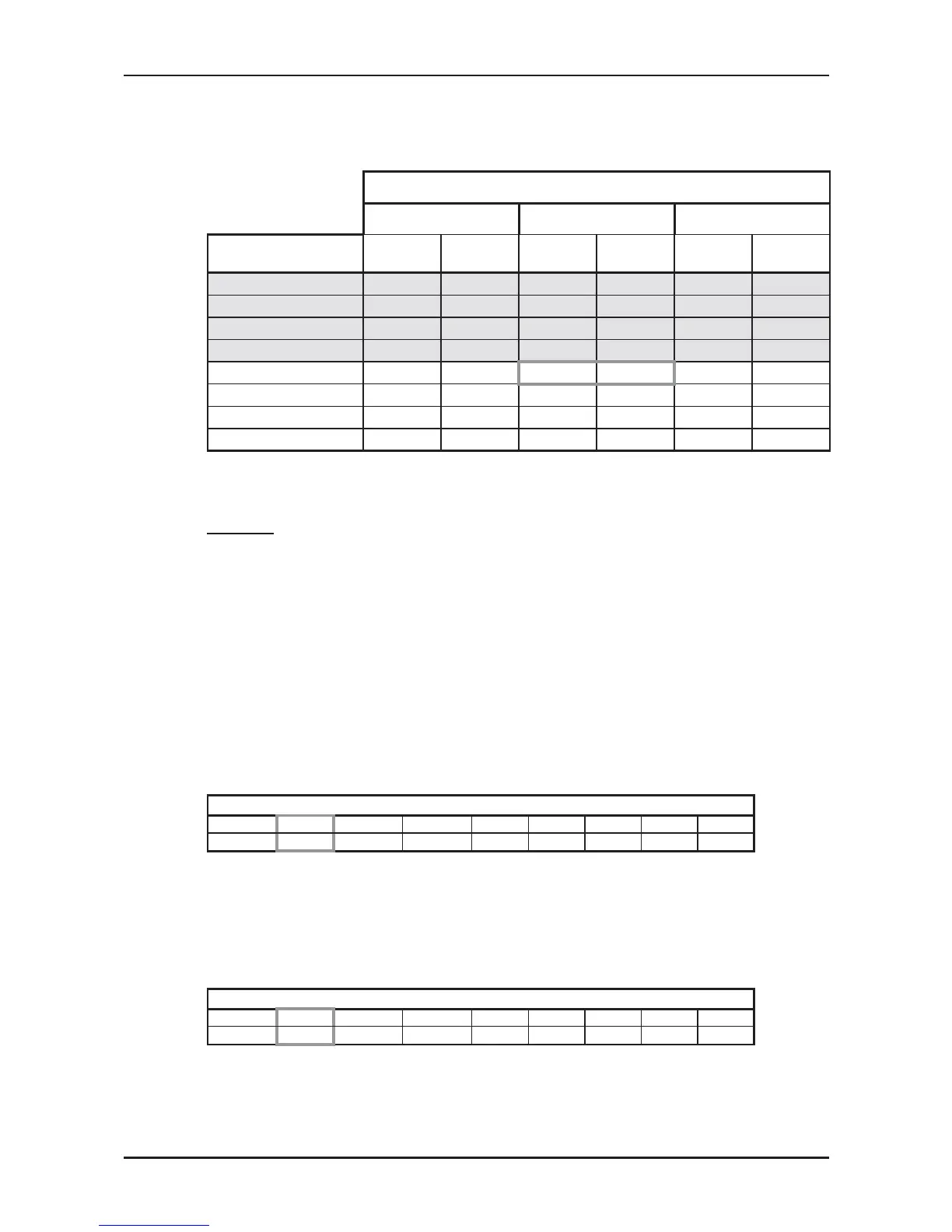
5.19.2 Heating Mode at 7.5m Tubing Connection.
230V : Indoor Fan at High Speed.
ENTERING AIR DB ID COIL ( °C)
15 20 25
ENTERING AIR WB
OU COIL (°C)
TH PI TH PI TH PI
-10 5.24 2.38 5.04 2.54 4.84 2.67
-7 5.64 2.44 5.44 2.58 5.24 2.72
-2 5.99 2.47 5.79 2.62 5.59 2.77
2 7.29 2.59
6.99 2.76
6.69 2.92
6 9.35 2.79 9.08 2.98 8.76 3.16
10 10.17 2.94
9.90 3.14
9.62 3.36
15 10.99 3.07 10.71 3.31 10.44 3.52
20 11.58 3.16 11.30 3.43 10.99 3.70
* the above chart includes the weighted deicing infleuence.
LEGEND
TH – Total Heating Capacity, kW
PI – Power Input, kW
WB – Wet Bulb Temp., (
o
C)
DB – Dry Bulb Temp., (
o
C)
ID – Indoor
OU – Outdoors
5.20 Capacity Correction Factor Due to Tubing Length
5.20.1 Cooling
TOTAL TUBING LENGTH (One Way)
3m
7.5m
10m 15m 20m 25m 30m 40m 50m
1.01
1
0.980 0.970 0.960 0.950 0.940 --- ---
* Minimum recommended tubing length between indoor and outdoor units is 3m.
5.20.2 Heating
TOTAL TUBING LENGTH (One Way)
3m
7.5m
10m 15m 20m 25m 30m 40m 50m
1.02
1
0.990 0.990 0.980 0.970 0.970 --- ---
* Minimum recommended tubing length between indoor and outdoor units is 3m.
 Loading...