EasyManua.ls Logo

Aiwa CX-NV900 User Manual

Aiwa CX-NV900
35 pages
To Next Page IconTo Next Page
Page #1 background imageLoading...
Page #1 background image
Question and Answer IconNeed help?

Do you have a question about the Aiwa CX-NV900 and is the answer not in the manual?

Aiwa CX-NV900 Specifications

General IconGeneral
TypeStereo Receiver
Tuning rangeFM, MW
Power Output100W per channel (8 ohms, 20Hz-20kHz, 0.08% THD)
Total Harmonic Distortion0.08% (20Hz-20kHz, 8 ohms)
Input Sensitivity2.5mV (MM), 150mV (line)
Dimensions430 x 142 x 300mm
Weight7.5kg
Signal to noise ratio100dB (line), 80dB (phono)

Summary

Specifications

Amplifier Specifications

Specifications for amplifier power output, harmonic distortion, inputs, and outputs.

Cassette Deck Specifications

Specifications for cassette deck track format, frequency response, and heads.

CD Player Specifications

Specifications for CD player laser, D-A converter, and signal-to-noise ratio.

Laser Safety During Servicing

Precaution to Replace Optical Block

Guidance on precautions to take when replacing the optical block to prevent damage.

Transistor Illustrations

Block Diagram 1 - Tuner Section (Main: HE,HR)

Block Diagram 2 - Main and Front Sections (Main/Front)

Wiring Diagram 1 - Main Section (Main: HE,HR)

Block Diagram 3 - Main Section (Main: LH,U)

IC Block Diagram 1

Block diagram illustrating the internal structure of IC HA12134A.

Schematic Diagram 1 - Main Section (Main: HE,HR)

IC Block Diagram 2

Wiring Diagram 3 - Main Section (Main: U)

IC Block Diagram 4

IC Description - LC866440W-5A39

Adjustment Procedures (Tuner and Deck)

Tuner Section Adjustments

Detailed adjustment procedures for the tuner section, including clock frequency and VT checks.

Deck Section Adjustments

Detailed adjustment procedures for the deck section, covering tape speed and azimuth.

Practical Service Figures

Tuner Section Service Figures

Service figures for the tuner section, including S/N, distortion, and sensitivity.

Deck Section Service Figures

Service figures for the deck section, covering tape speed, wow/flutter, and noise levels.
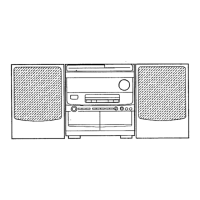
FL Grid Assignment and Anode Connection

Mechanical Exploded View

Tape Mechanism Exploded View

Spring Application Position

Accessories and Package List

Reference Name List

Related product manuals