EasyManua.ls Logo

Aiwa CX-ZL700 User Manual

Aiwa CX-ZL700
46 pages
To Next Page IconTo Next Page
Page #1 background imageLoading...
Page #1 background image
SERVICE MANUAL
DATA
COMPACT DISC STEREO
CASSETTE RECEIVER
BASIC TAPE MECHANISM : 2ZM-3MK2 PR5NM
BASIC CD MECHANISM : 6ZG-1 ZRDM
Z-L700
Z-L800
U
LH
S/M Code No. 09-004-422-7R1
REVISION
• If requiring information about the CD mechanism, see Service Manual of 6ZG-1,
(S/M Code No. 09-001-338-7N2).
• This Service Manual is the “Revision Publishing” and replaces “Simple Manual”
Z-L700 (U) / Z-L800 (LH), (S/M Code No. 09-002-422-7T1).
Z-L700
SPEAKER
SYSTEM
CD
CASSEIVER
SX-WZL700CX-ZL700
RC-ZAS12
STEREO
TURNTABLE
Z-L800
CX-ZL800 SX-WZL800
REMOTE
CONTROLLER
PX-E860
-
• If requiring information about the Stereo Turntable, see Service Manual of
PX-E860 (U), (S/M Code No. 09-993-322-0R1).
All manuals and user guides at all-guides.com
all-guides.com
Question and Answer IconNeed help?

Do you have a question about the Aiwa CX-ZL700 and is the answer not in the manual?

Aiwa CX-ZL700 Specifications

General IconGeneral
TypeStereo Receiver
Tuning rangeFM, MW
Power output40 watts per channel into 8Ω (stereo)
Frequency response20Hz to 20kHz
Total harmonic distortion0.5%
Input sensitivity2.5mV (MM), 150mV (line)
Dimensions430 x 140 x 300mm
Weight7.8kg
Channel separation50dB
Speaker Impedance8Ω to 16Ω

Summary

Product Specifications

Amplifier Section Specifications

Power output, distortion, inputs, and outputs for the amplifier section.

Safety Precautions

Laser Beam Safety During Servicing

Warnings and procedures for safe laser handling during servicing.

Optical Block Replacement Precautions

Precautions regarding electrostatic discharge when replacing optical blocks.

Pre-Repair Procedures

Power Supply Capacitor Discharge Procedure

Procedure to safely discharge electrolytic capacitors before repair.

Microcomputer Troubleshooting and Checks

Checks for microcomputer defects, focusing on HOLD terminal and soldering.

Microcomputer Reset Procedure

Procedure for performing a forced reset on the microcomputer.

Integrated Circuit Diagrams

Adjustment Procedures

Tuner Section Adjustment Procedures

Procedures for clock frequency, AM VT, AM tracking, and FM VT checks.

Cassette Deck Adjustment Procedures

Adjusting tape speed, azimuth, frequency response, and sensitivity.

Front Section and MICON OSC Adjustment

Calibration for front panel controls and MICON OSC.

Integrated Circuit Pin Descriptions

Mechanical Assembly and Parts

Speaker Servicing

Speaker Disassembly Instructions

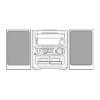
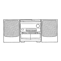
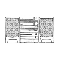
Step-by-step instructions for disassembling speaker units.

Related product manuals