EasyManua.ls Logo

Aiwa HS-J400 Service Manual

Aiwa HS-J400
25 pages
To Next Page IconTo Next Page
Page #1 background imageLoading...
Page #1 background image
AIWA’
S/M
Code
No.
84-013
DATE
OF
ISSUE
6/1984
SERVICE
MANUAL
MODEL
NO.
HS-J7,JO07,J400
FM/AM
STEREO
RADIO
CASSETTE
RECORDER
Y-EARHAU
Az
&
5
#2
#
AF
G-
-
G-
-
TYPE.
D,Y,
“OR
GROMRES+HIKED
TA,
HE
FOUR.
wT
PFROWB*
FOTKS
Lo
1.
AN
yABRM,.
EMIS,
EA-ARINIW
SORRNLFRBL
TMA
COBO,
2.
BRI
-L
OME.
BTUBAD
BMS
APIS.
NG
VP
OMAR
KRY
Fe
BL
THUY
bRMCLOPVUAET
SR,
3.
ROSABISHERI
CDT
AL
THOR,
1)
4-7
O34
FAST
AKRE
2)9
FT
V—OFAMLRAURRKAES
3)74
7
—OfSKR
4
)
BABA
AR
ED
ERT
IARE
4.
AHI
ALAERO
MER
BIA
l)N\y
FABER
COSEROBA,
BRAD,
SRORRES
OwWReyO£TOT.
RPH,
EH,
EU
FA-F-,
ey
FARBVMADSE
PLAN
CBT
OR.
2Z)NILKL
PLES.
Fer
FARBY,
EY
FA-7-SOH
SD
(DAM.
F-VPHEAM)
CAT,
FI)
-A2BeArN
Et
Sc
A277.
DYERRSORR
CCSD
CERBT
aH.
Z)A
TILA
SRB.
thes
-—
YA
OTH
RAL
&
PAIL
TF
OA,
BSR
(1
~
258)
Kk
eEOTH
OR,
PIF
S-BlSee.
EY
FA—F—,
MBAR
T
S
.
A)A-—
VY
ARITU
TOR
EU
LD,
RY
RGGI
F-Dy
Ve
—SiL.
FT
LRA.
RETO
TRL
OMe
RIBS
aR.
S)tey
b
MME
S—
VIS
TIERRA
EARL.
HEARS
YUAN
Y
RUBS
VIS.
RROTEREE
FRU
AAA~RALPAR.,
BNR
euwseneeSERlae#K,
#2
Fk
:
82681-1001(DS)
82681-1011(DR)
82681-1021(DBL)
82681-1051(DYL)
82681
-1081(DGR)
82681
-1091(DP)
Follow
the
instructions
carefully,
which
will
allow
the
user
to
optimise
the
products’
performance
and
give
many
years
of
serivce.
.
No
illegibility
shall
be
given
to
the
specification
plate,
the
cau-
tion
labels,
the
fuse
labels
and
others.
.
When,
on
pattern
sides
of
circuit
boards,
additional
repair-parts
have
been
made
up,
the
parts
shall
be
firmly
glued
to
circuit
boards
or
other
components,
unless
the
parts
can
be
attached
firmly.
.
The
following
matters
shall
be
maintained
as
they
are,
when
repairing.
1)
Soldering
of
lead-wire
ends
2)
Wiring
and
holding
of
lead-wires
with
wire-clips
and
binders
3)
Materials
of
lead-wires
4)
Location
of
all
kinds
of
insulators
.
General
instructions
for
mechanism
repair
1)
The
heads,
capstan
and
pinch
roller
shall
be
cleaned
of
good
quality
alcohol
after
repaired,
because
dirty
heads
shall
cause
distorted
sounds
while‘dirty
capstan
and
pinch
roller
shall
occur
wow/flutter
and
take-up
fault.
2)
Lubricants
been
stained
the
surfaces
of
transmitting
portion
of
the
belts,
idlers,
capstan
and
pinch
roller
shal!
be
removed,
because
slippery
and
faulty
tape
travel
shall
be
caused.
3)
When
oiling,
only
one
or
two
drops
shall
be
applied
so
as
not
to
run
over
and
be
dispersed.
Note
should
be
taken
of
the
metal
fitting
for
the
capstan
and
rotating
portions
of
the
idlers
and
pinch
roller,
especially.
4)
E-rings
and
poly
slider
washers
shall
be
replaced
with
new
ones,
if
once
those
have
been
removed.
No
re-utilization
due
to
unreliability.
5)
Regular
spare-parts
shall
always
be
used
for
repair,
because
using
irregular
parts
and
tampering
with
the
products
shall
cause
deterioration,
mulfunction
and
damage.
Question and Answer IconNeed help?

Do you have a question about the Aiwa HS-J400 and is the answer not in the manual?

Aiwa HS-J400 Specifications

General IconGeneral
BrandAiwa
ModelHS-J400
CategoryCassette Player
LanguageEnglish

Summary

General Repair and Maintenance Guidelines

Circuit Board Repair Procedures

Securely glue added parts to circuit boards or components.

Mechanism Repair Precautions

Clean heads, capstans, pinch rollers. Avoid lubricants on moving parts.

Radio Section Specifications

Radio Circuitry and Reception Specs

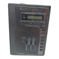
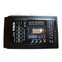
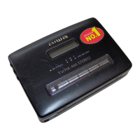
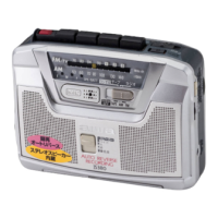
Details on superheterodyne circuitry, FM/AM frequencies, and sensitivity.

Tape Recorder Section Specifications

Wow/Flutter, Auto-Stop, and Torque

Tape speed fluctuations, auto-stop function, and torque specifications.

Detailed Radio Section Specifications

Detailed Tape Recorder Specs

Adjustment Procedures - Radio Tuning

AM/FM IF and Tracking Adjustments

Procedures for adjusting IF and tracking for AM/FM bands.

AM/FM Frequency Range Adjustments

How to adjust the frequency range for AM and FM.

Leaf Switch Adjustment

Adjusting the leaf switch for proper gap.

Dolby Level and VCO Adjustments

Adjusting Dolby level and VCO frequency.

Main Circuit Board - Pattern Side Schematic

Main CB Pattern Layout

Visual layout of components and traces on the main PCB.

Circuit Board Wiring Diagrams

Main Circuit Board Wiring

Wiring details for the main circuit board.

Circuit Board Wiring Details

Main CB Wiring Details

Detailed wiring connections on the main circuit board.

Tape Speed Adjustment

Tape Speed Adjustment Procedure

Procedure to adjust tape speed.

PC Board Pattern Diagram

Main PC Board Pattern

Printed circuit board component and trace layout.

Mechanism Functions - Bottom Plate Assembly

Removing Bottom Plate Assembly

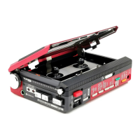
Steps to remove the bottom plate assembly.

Installing Bottom Plate Assembly

Steps for correctly installing the bottom plate assembly.

Mechanism Functions - Transmission Processes

FWD PLAY Lever Movement Process

Lever movement path during forward play.

FWD PLAY Gear Transmission Process

Gear transmission path during forward play.

REVERSE PLAY Gear Transmission Process

Gear transmission path during reverse play.

Mechanism Functions - Reverse Operations

Manual Reverse Transmission Path

Lever and gear path for manual reverse.

Auto Reverse Transmission Path

Lever and gear path for auto reverse.

Reverse Mode Selection

Correct positioning for continuous/return auto-reverse.

Mechanism Functions - Auto Stop and FF

Auto Stop Operation at Tape End (Record)

Mechanism action when tape ends during recording.

FF Operation - Gear Transmission

Gear movement path during fast forward.

FF Operation - Lever Movement

Lever movement path during fast forward.

Mechanism Functions - REW and Spring Application

REW Operation - Gear Transmission

Gear movement path during rewind.

REW Operation - Lever Movement

Lever movement path during rewind.

Disassembly Instructions - Cabinet and Lid

Removing Rear Cabinet

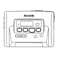
Steps to remove the rear cabinet.

Removing Cassette Lid

Steps to remove the cassette lid.
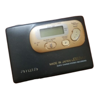
Disassembly Instructions - Main Board and Panel

Related product manuals