Do you have a question about the Aiwa HS-JX609 and is the answer not in the manual?
Details frequency range, output, power sources, battery life, dimensions, and weight.
Identifies the basic tape mechanism (2ZM-2 R1) and type (AH).
Steps for removing and reinstalling the motor assembly and related parts.
Procedure to check mechanism operation after reinstallation.
Precautions to prevent damage during motor reinstallation, especially to the FP Coil.
List of IC part numbers, names, and descriptions.
List of transistor part numbers, names, and descriptions.
List of diode part numbers, names, and descriptions.
List of components on the main circuit board.
List of capacitor part numbers, names, and descriptions.
Explanation of the coding system for chip resistors, including dimensions and tolerance.
Schematic showing component placement and connections on the main circuit board.
Schematic showing component placement and connections on the head flex circuit board.
Schematic showing component placement and connections on the tuner flex circuit board.
Detailed circuit diagram for the main control board.
Detailed circuit diagram for the tuner flex circuit board.
Detailed circuit diagram for the head flex circuit board.
Schematic showing component placement and connections on the tuner circuit board.
Diagram showing the connection points between the tuner circuit board and the main circuit board.
Detailed circuit diagram for the tuner circuit board.
Diagram showing LCB connections and display interface details.
Steps for adjusting AM Intermediate Frequency and Voltage Tuning.
Procedure for adjusting AM tracking for accurate frequency response.
Steps for adjusting FM Voltage Tuning and tracking.
Specifications for wow/flutter, torque, S/N ratio, distortion, and frequency response.
Specifications for sensitivity, IF, and stereo separation.
Procedures for tape speed adjustment; notes no azimuth adjustment.
Detailed description of each pin's name, I/O type, and function.
Explanation of pins for mode selection and band switching.
Details on alarm, remote off, stop, F/R, mute, FM out, and other special functions.
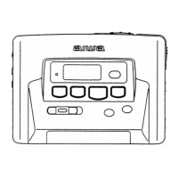
Exploded view showing major mechanical parts and their assembly order.
Identification of the Tuner CB, SH, CHAS N, SH, PWB, and MAIN CB within the assembly.
List of mechanical parts with reference numbers, part numbers, and descriptions.
List of battery box and holder components.
List of knobs, buttons, and plates used in the assembly.
Exploded view of the tape transport mechanism, showing part locations.
Identification of Head Flex CB and other components within the tape mechanism.
List of tape mechanism parts with reference numbers, part numbers, and descriptions.
List of springs and gears used in the tape mechanism.
List of levers and linkages used in the tape mechanism.
Diagrams showing the correct application position for various springs.
Illustrations of specific spring types (SPR-T, SPR-C, SPR-E) and their locations.
Illustrations of common transistor types and their part number mappings.
Block diagram illustrating the internal functions of the LB1674V IC.
List of accessories and package contents with part numbers.
List of abbreviations and reference names for electrical components.
List of abbreviations and reference names for mechanical components.
| Tape Speed | 4.8 cm/s |
|---|---|
| Battery | 2 x AA batteries |
| Power Supply | 3V DC |
| Headphone Output | 3.5 mm stereo jack |
| Type | Cassette Player/Recorder |
| Noise Reduction | Dolby B |
| Signal To Noise Ratio | 58dB (Dolby NR on) |
| Playback Modes | Normal |
| Included Accessories | headphones |
| Frequency Response | 40 Hz - 12, 000 Hz (Metal tape) |