Do you have a question about the Aiwa HS-T50 and is the answer not in the manual?
Technical specifications for the HS-T50 model, including frequency, output, and power.
Technical specifications for the HS-T55 model, including frequency, output, and power.
Technical specifications for the HS-T51 model, including frequency, output, and power.
Explains the structure and meaning of chip resistor part numbers.
Details sensitivity, intermediate frequency, and stereo separation for the radio.
Details wow/flutter, torque, S/N ratio, distortion, and frequency response for the tape player.
Detailed description of the TC9308AF-029 IC pins and their operational roles.
Step-by-step instructions for adjusting radio VT, IF, and tracking parameters.
Step-by-step instructions for adjusting tape azimuth, speed, and motor load.
Covers FM VT, AM IF, AM Tracking, and FM Tracking adjustments.
Covers Azimuth, Tape Speed, and Motor Load adjustments.
Identifies specific test points and components for radio tuning and calibration.
Identifies specific test points and components for tape player calibration.
Visual representation of the main internal components and their assembly.
Visual diagram showing the assembly of mechanical parts.
Illustrates the assembly of various mechanical sub-assemblies.
Lists the items included in the product package with the device.
| Brand | Aiwa |
|---|---|
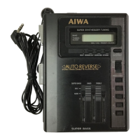
| Model | HS-T50 |
| Category | Cassette Player |
| Language | English |