Do you have a question about the Aiwa HS-TA166 and is the answer not in the manual?
Details differences between HS-TA165/HS-TA166 models and their variants.
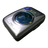
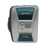
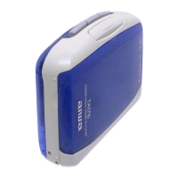
Lists available color options for the HS-TA166 models.
Lists key technical parameters like frequency range, output, power, dimensions, and weight.
Details included accessories and the package contents.
Lists IC, Transistor, Diode, and Main C.B. components with part numbers.
Provides visual representations of common transistors used in the device.
Illustrates the wiring layout and connections on the main circuit board.
Presents the detailed schematic diagram for the main circuit board.
Procedures for adjusting AM/FM frequency range and tracking.
Procedures for tape speed and head azimuth adjustments.
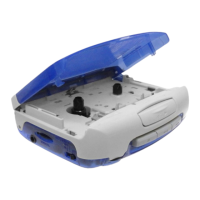
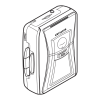
Visual exploded view of the mechanical components.
List of all mechanical parts with part numbers and descriptions.
Table mapping color symbols to actual color names.
Lists parts for P15NC and P16NC tape mechanisms with numbers and descriptions.
Lists parts for P13NC2 tape mechanism with numbers and descriptions.
This document is a supplement to the service manuals for the HS-TA165 and HS-TA166 models, specifically covering the HS-TA166 (YH1BC, YH1LMC) in Black and Metallic Blue colors, and the HS-TA166 (YL1LTC, YL1BLTC, YL1BGTC, YL1BYTC) in Transparent Blue, Transparent Green, and Transparent Yellow colors. It provides additional data for these specific variants, building upon the information found in the main service manuals (S/M Code No. 09-001-406-0N1 for HS-TA165/HS-TA166 YH, YZ, YJ, and S/M Code No. 09-99B-406-0R3 for HS-TA166 YL).
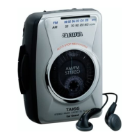
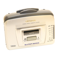
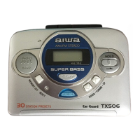
The device described is a Stereo Radio Cassette Player, designed for portable audio playback and radio reception.
The device functions as a personal stereo, allowing users to:
The service manual supplement outlines several key adjustments and lists electrical and mechanical parts for maintenance and repair.
The adjustment section details procedures for optimizing the device's performance:
Key electrical components are listed with their part numbers and descriptions, including:
The manual provides exploded views and detailed parts lists for the mechanical components, including:
A comprehensive table defines the color codes used in the parts lists, covering various standard and transparent colors, as well as metallic finishes. This is crucial for ordering correct replacement parts that match the specific aesthetic variants of the HS-TA166.
The document emphasizes that design and specifications are subject to change without notice.
| Brand | Aiwa |
|---|---|
| Model | HS-TA166 |
| Category | Cassette Player |
| Language | English |