EasyManua.ls Logo

Aiwa NSX-D707 Service Manual

Aiwa NSX-D707
46 pages
To Next Page IconTo Next Page
Page #1 background imageLoading...
Page #1 background image
NSX-D/07
COMPACT
DISC
STEREO
SYSTEM
e
BASIC
TAPE
MECHANISM
:
2ZM
3PR2N
eee
a
e
BASIC
CD
MECHANISM
:
KSM
2101ABM
Snare!
CASSETTE
REMOTE
DECK
SPEAKER
TUNER
CD
PLAYER
CONTROLLER
a
RX
N707
FD
N909
RC
TN707
SX
N707
RX
N707
FD
N909
RC
TN707
SX
N707
(TYPE
:
U)
RX
N707
FD
N707
RC
TN707
SX
N707
S/M
Code
No.
09
938
026
40T
AMPLIFIER
SYSTEM
NSX
D707
(TYPE
:
HE,HR,LH)
(TYPE
:
E,K,Z)
—_
=
=
es
Oo
———
as
rH)
SP)
Question and Answer IconNeed help?

Do you have a question about the Aiwa NSX-D707 and is the answer not in the manual?

Aiwa NSX-D707 Specifications

General IconGeneral
BrandAiwa
ModelNSX-D707
CategoryStereo System
LanguageEnglish

Summary

Specifications

Tuner/Amplifier RX-N707 Specifications

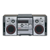
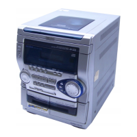
Detailed specifications for FM, AM, MW, LW, Timer, and Amplifier sections.

Cassette Deck/CD Player FD-N909, N707 Specifications

Technical details for cassette deck and CD player functions.

Speaker SX-N707 Specifications

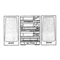
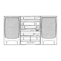
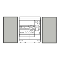
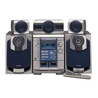
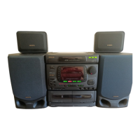
Speaker system specifications including impedance, power, and dimensions.

Common Section Specifications

Power requirements and overall system dimensions/weight.

Electrical Main Parts List (RX-N707)

IC Components

List of Integrated Circuits used in the RX-N707 unit.

Transistors

List of transistors with part numbers and descriptions.

Diodes

List of diodes with part numbers and descriptions.

Capacitors (Main C.B.)

List of capacitors on the main circuit board.

Electrical Main Parts List (Capacitors)

Capacitors (Continued)

Continuation of the capacitor list from page 4.

Electrical Main Parts List (Other Components)

Coils and Inductors

List of coils and inductors used in the unit.

Fuses, Filters, and Trimmers

List of fuses, filters, and trimmer capacitors.

Switches and Connectors

List of switches and connectors.

Electrical Main Parts List (Continued)

Miscellaneous Components

Various miscellaneous electrical parts.

Transistor Illustrations

Visual representation of transistor pinouts.

Chip Resistor Part Code

Explanation of the coding system for chip resistors.

Schematic Diagram - 1 (Main Board)

Wiring Diagram - 1 (Main Board)

Schematic Diagram - 2 (Main Board - E, K)

Wiring Diagram - 2 (Main Board - E, K)

Schematic Diagram - 3 (Main Board - Z)

Wiring Diagram - 3 (Main Board - Z)

Schematic Diagram - 4 (Front Panel)

Wiring Diagram - 4 (Front Panel)

Wiring Diagram - 5 (Power)

FL Grid Assignment and Anode Connection

IC Description: CXP82324-1410

IC Block Diagrams

IC, LA1831M Block Diagram

Functional block diagram for the LA1831M IC.

IC, LA3607 Block Diagram

Functional block diagram for the LA3607 IC.

IC Block Diagrams (Continued)

IC, NJU9701D Block Diagram

Functional block diagram for the NJU9701D IC.

IC, NJU7305 Block Diagram

Functional block diagram for the NJU7305 IC.

Electrical Adjustment (Tuner)

Tuner Section Initial Conditions

Initial settings for tuner adjustment procedures.

Clock Check Adjustment

Procedure for adjusting the clock signal in the tuner.

MW VT Check (HE,LH,U ONLY)

Checking the MW voltage-tuned circuit for specific models.

MW VT Adjustment (E,K,Z ONLY)

Adjusting the MW voltage-tuned circuit for specific models.

LW VT Adjustment (E,K,Z ONLY)

Adjusting the LW voltage-tuned circuit for specific models.

FM VT Adjustment

Adjusting the FM voltage-tuned circuit.

MW, LW Tracking Adjustment (E,K,Z ONLY)

Tracking adjustments for MW and LW signals.

Practical Service Figure (Tuner)

FM Section Practical Figures

Performance figures and specifications for the FM section.

AM (MW) Section Practical Figures

Performance figures and specifications for the AM/MW section.

LW Section Practical Figures (E,K,Z)

Performance figures and specifications for the LW section.

Mechanical Exploded View 1/1

Mechanical Parts List 1/1

Laser Safety Precautions

Optical Block Replacement Precautions

Electrical Main Parts List (Continued)

Electrical Main Parts List (Continued)

Mechanical Exploded View 1/2

Mechanical Parts List 2/2

Tape Mechanism Exploded View 1/1

Tape Mechanism Parts List 1/1

CD Mechanism Exploded View 1/1

Spring Application Position

Speaker List (SX-N707)

Disassembly Instructions (SX-N707)

Steps for disassembling the SX-N707 speaker system.

Accessories and Package List

Reference Name List

FL Grid Assignment and Anode Connection

IC Description: μPD78043GF-032

Electrical Adjustment (Deck)

Tape Speed Adjustment

Procedure to adjust tape speed for the deck.

Head Azimuth Adjustment

Adjusting the head azimuth for optimal playback.

PB Frequency Response Check

Checking playback frequency response.

PB Sensitivity Adjustment

Adjusting playback sensitivity.

REC/PB Frequency Response Adjustment

Adjusting record/playback frequency response.

Practical Service Figure (Deck)

Electrical Adjustment (CD Player)

VCO Frequency Adjustment

Adjusting the Voltage Controlled Oscillator frequency.

Focus Bias Adjustment

Adjusting the focus bias for the optical pickup.

RF Waveform Check

Checking the RF waveform for proper CD playback.

Electrical Adjustment (CD Player - Continued)

Tracking Balance Adjustment

Adjusting the balance between tracking and focus.

Tracking Gain Adjustment

Adjusting the tracking gain for optimal performance.

Electrical Adjustment (CD Player - Continued)

Tracking Gain Adjustment (Simple Method)

Simplified method for adjusting tracking gain.

Mechanical Exploded View 1/2

Mechanical Parts List 1/2

Mechanical Exploded View 2/2

Mechanical Parts List 2/2

Tape Mechanism Exploded View 1/1

Tape Mechanism Parts List 1/1

CD Mechanism Exploded View 1/1

Spring Application Position

Speaker List (SX-N707)

Disassembly Instructions (SX-N707)

Steps for disassembling the SX-N707 speaker system.

Accessories and Package List

Reference Name List

Related product manuals