Do you have a question about the Aiwa NSX-D70 and is the answer not in the manual?
Comprehensive technical specifications for tuner, amplifier, cassette, CD, speaker, and general system functions.
Essential safety guidelines to prevent eye injury from laser radiation during servicing operations.
Critical steps before repair, including capacitor discharge, microcomputer checks, reset, and soldering confirmation.
Chip resistor part codes and transistor illustrations for component identification.
Wiring diagrams for main, jack, front, CD, deck, and power transformer (PT) sections.
Schematic diagrams for amplifier, tuner, jack, front/deck/CD, and power transformer (PT) circuits.
Block diagrams and detailed pin descriptions for principal integrated circuits.
Grid assignment and anode connection details for the FL display unit.
Step-by-step instructions for performing adjustments on tuner and deck mechanisms.
Procedures for entering and utilizing the CD test mode for diagnostic purposes.
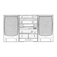
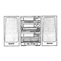
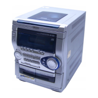
Visual guides illustrating the exploded views of the main unit and tape mechanism.
Step-by-step instructions for the safe disassembly of speaker units.
A reference table mapping basic color symbols to their corresponding color names.
| Tuner | AM/FM |
|---|---|
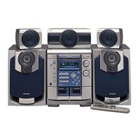
| Remote Control | Yes |
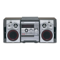
| CD Player | 3-CD Changer |
| Cassette Deck | Dual, Auto Reverse |
| Functions | CD, Cassette, Radio |
| Amplifier Output Power | 60W per channel |
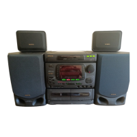
| Type | Mini Hi-Fi System |
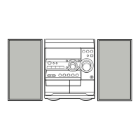
| Speakers | 3-Way |