EasyManua.ls Logo

Aiwa NSX-D737 Service Manual

Aiwa NSX-D737
50 pages
To Next Page IconTo Next Page
Page #1 background imageLoading...
Page #1 background image
AnTIA
il
COMPACT
DISC
STEREO
SYSTEM
*
BASIC
TAPE
MECHANISM:
2ZM-3PR2N.
*
BASIC
CD
MECHANISM:
KSM-2101ABM
ana
SERVICE
NSX-D737
¢
TYPE?
HE,LH.EE.
K.U.EEZ
REVISION
PUBLISHING
|
]
“a
|
>
T
|
|
gysrem
|
AMPLIFIER
|
CASSETTE
|
ReMoTe
|
wath
teal
tuner
|
PECK
conTROLLER
CD
PLAYER
|
ge
ate
:
=
i
NSX-D737
|
-N737.
|
FD-N939_
|
RC-TN707
|
SX-N737
(TYPE:HELH)|
P*N
tal
(TYPE:
RX-N737
|
FD-N939
|
RC-TN707
|
SX-N737
EE,K,U,EEZ)
as
SIM
Code
No.
09-946-055-60T
4
<r
Zz
—<
=
‘am
_—
ae
aa
Py.
Question and Answer IconNeed help?

Do you have a question about the Aiwa NSX-D737 and is the answer not in the manual?

Aiwa NSX-D737 Specifications

General IconGeneral
CD PlayerYes
Cassette DeckDual cassette deck
Radio TunerAM/FM
Remote ControlYes
Equalizer5-band graphic equalizer
TypeMini Hi-Fi System
CD Changer3-disc
Speakers2-way speakers

Summary

AIWA NSX-D737 Service Manual Overview

Revision Publishing Information

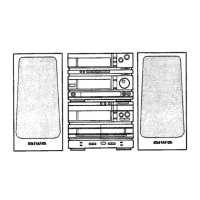
Details model variations and component cross-references.

Product Specifications

Tuner/Amplifier Specifications

Detailed electrical and performance parameters for the tuner/amplifier section.

Cassette Deck/CD Player Specifications

Technical data for the tape deck and CD player mechanisms.

Speaker Specifications

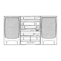
Details on the speaker system's impedance, power, and dimensions.

Common Section Specifications

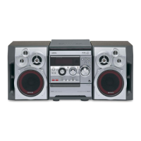
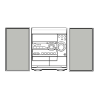
General specifications applicable to the entire system, including power and dimensions.

RX-N737 Electrical Main Parts List

IC Components

List of integrated circuits used in the RX-N737 model.

Transistors and Diodes

Lists transistors, diodes, and zener diodes for the RX-N737.

Capacitors (Main C.B)

List of capacitors on the main circuit board for RX-N737.

Transistor Pinout Illustrations

Common Transistor Diagrams

Visual representation of common transistor pin configurations.

Block Diagrams - LH, HE, U Models

Block Diagram 1 (LH, HE, U)

System block diagram for specific LH, HE, U model variations.

Schematic Diagrams - Main (LH, HE, U)

Schematic Diagram 1 (Main)

Circuit schematic for the main unit of LH, HE, U models.

Wiring Diagrams - Main (LH, HE, U)

Wiring Diagram 1 (Main)

Wiring layout for the main unit of LH, HE, U models.

Wiring Diagrams - Front Section

Wiring Diagram 3 (Front)

Wiring layout for the front panel components.

Wiring Diagrams - Power and Display

Wiring Diagram 4 (Power)

Power wiring connections for the system.

FL Grid Assignment/Anode Connection

Details on FL display grid assignments and anode connections.

IC Descriptions

LC7218M IC Description

Pinout and function description for the LC7218M IC.

IC Block Diagrams

BU4094B Block Diagram

Block diagram and truth table for the BU4094B IC.

IC Block Diagrams (Continued)

M65830AFP Block Diagram

Block diagram for the M65830AFP IC.

Tuner Section Electrical Adjustments

Clock Check and MW VT Check

Procedures for clock check and MW VT verification.

MW, LW, and FM VT Adjustments

Adjustments for MW, LW, and FM voltage variations.

Tracking Adjustment Procedures

Steps for adjusting MW, LW, and FM tracking.

Tuner Section Performance Figures

FM Section Performance

Key performance metrics and specifications for the FM reception section.

AM (MW) and LW Section Performance

Performance metrics for AM (MW) and LW reception sections.

Mechanical Exploded View 1/1

Mechanical Parts List 1/1

FD-N939 Servicing Cautions

Single Unit Repairing Method

Instructions for repairing the FD-N939 unit when serviced independently.

Laser Safety Precautions

Laser Beam Warnings and Cautions

Critical warnings and safety guidelines for servicing laser components.

Optical Block Replacement Precautions

Safety procedures and precautions for replacing the optical block.

Chip Resistor Part Coding

Explanation of the coding system for chip resistors.

Electrical Main Parts List (Cont.)

IC Components (Cont.)

Continuation of the list of integrated circuits.

Capacitors (C.B)

List of capacitors on various circuit boards.

CD Mechanism Block Diagrams

Block Diagram 1 (CD)

System block diagram for the CD mechanism.

Deck Mechanism Block Diagrams

Block Diagram 2 (Deck)

System block diagram for the tape deck mechanism.

CD Mechanism Schematic Diagrams

Schematic Diagram 1 (CD)

Circuit schematic for the CD mechanism.

CD Mechanism Wiring Diagrams

Wiring Diagram 1 (CD)

Wiring layout for the CD mechanism.

Deck Mechanism Schematic Diagrams

Schematic Diagram 2 (Deck)

Circuit schematic for the tape deck mechanism.

Deck Mechanism Wiring Diagrams

Wiring Diagram 2 (Deck)

Wiring layout for the tape deck mechanism.

FL Display Connections

Grid Assignment and Anode Connection

Details on FL display grid assignments and anode connections.

IC Descriptions (Continued)

SM5875BM IC Description

Pinout and function description for the SM5875BM IC.

IC Block Diagrams (Continued)

BU4094B Block Diagram and Truth Table

Block diagram and truth table for the BU4094B IC.

IC Block Diagrams (Continued)

BA6397FP Block Diagram

Block diagram for the BA6397FP IC.

Deck Section Electrical Adjustments

Tape Speed and Head Azimuth Adjustments

Procedures for tape speed and head azimuth adjustments.

PB Frequency Response and Sensitivity

Procedures for PB frequency response and sensitivity adjustments.

REC/PB Frequency Response Adjustment

Procedure for adjusting REC/PB frequency response.

Deck Section Performance Figures

Deck Performance Metrics

Key performance specifications for the tape deck section.

CD Section Electrical Adjustments

VCO Frequency and Focus Bias Adjustments

Procedures for VCO frequency and focus bias adjustments.

RF Waveform Check

Procedure for checking the RF waveform.

CD Mechanism Adjustments

Tracking Balance and Gain Adjustments

Procedures for adjusting tracking balance and gain.

Mechanical Exploded View 1/2

Mechanical Parts List 2/2

Tape Mechanism Exploded View

Tape Mechanism Parts List

CD Mechanism Exploded View

CD Mechanism Parts List

Spring Application Position

SX-N737 Speaker List and Disassembly

Speaker Disassembly Instructions

Step-by-step guide for disassembling the speaker units.

Accessories and Package List

Reference Name List

Related product manuals