Do you have a question about the Aiwa NSX-TR99 and is the answer not in the manual?
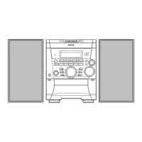
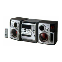
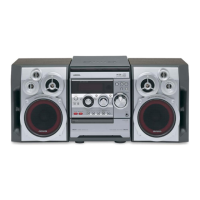
Technical specifications for the main unit, tuner, amplifier, CD player, and speakers.
Safety guidelines for laser handling and optical block replacement procedures.
Essential steps before repair, including capacitor discharge and microcomputer checks.
Lists of components for accessories, electrical, mechanical, tape, speaker, and other parts.
Visual identification of transistors used in the unit with their pin configurations.
Detailed circuit diagrams showing the electronic connections for various system sections.
Diagrams illustrating internal wiring routes and connections between circuit boards.
Guide to activating and using diagnostic test modes for the CD player.
Grid assignment for the front display and pin connections for troubleshooting.
Functional diagrams and pinout details for key integrated circuits.
Visual breakdown of mechanical assemblies for disassembly and reassembly.
List of primary mechanical components with their respective part numbers.
Exploded view and parts list for the tape transport mechanism.
Instructions for speaker disassembly and list of speaker components.
Reference table for color codes used in diagrams and parts identification.
Lists of miscellaneous parts not categorized elsewhere.
Specific lists of parts for the CD mechanism assemblies.
List of electrical components for the 3CD mechanism.
List of general electrical components, including resistors and transistors.
Visual identification of transistors used in the unit with their pin configurations.
High-level functional overview of the system's major blocks.
Illustrates internal wiring connections between circuit boards.
Detailed circuit diagrams showing the electronic connections for various system sections.
Visual representations of signal waveforms at critical test points for diagnosis.
Functional diagrams illustrating the internal structure of specific ICs.
Detailed pin functions and descriptions for integrated circuits (LC78645).
Visual breakdown of CD mechanism components for identification.
Specific lists of parts for the CD mechanism assembly (BZG-5).
List of parts for the KSM-2131FAM CD mechanism.
Procedures for adjusting AM and FM tuner circuits for optimal reception.
Detailed steps for calibrating AM reception and tracking circuits.
Detailed steps for calibrating FM reception, tracking, and separation.
Procedures for adjusting tape speed, wow/flutter, azimuth, and frequency response.
Procedure for adjusting the clock frequency in the front control section.
| Type | Stereo System |
|---|---|
| CD Player | Yes |
| Cassette Deck | Yes |
| Radio Tuner | AM/FM |
| Surround Sound | No |
| Remote Control | Yes |