Do you have a question about the Aiwa NSX-VC38 and is the answer not in the manual?
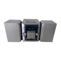
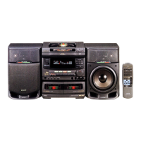
Details specifications for the primary CX-NVC38 unit.
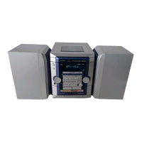
Details specifications for the SX-NBL25 speaker system.
Details specifications for the cassette deck section.
Provides essential safety warnings regarding laser beam exposure during servicing.
Outlines necessary precautions for safely replacing the optical block.
Details the procedure for safely discharging electrolytic capacitors before repair.
Explains how to check the HOLD terminal of the microcomputer for proper operation.
Describes the forced-reset procedure for the microcomputer to check its functionality.
Lists integrated circuit (IC) parts used in the main electrical system.
Lists transistor components used in the main electrical system.
Lists diode components used in the main electrical system.
Illustrations showing the pinout and appearance of various transistors.
Details the grid assignment for the FL display unit.
Specifies the anode connection points for the FL display unit.
Details the pin connections for the FL display unit.
Shows the wiring connections for the main unit (Part 1).
Presents the main unit schematic diagram (Part 1).
Shows the wiring connections for the front unit.
Presents schematic diagrams for the front and deck sections.
Shows the wiring connections for the amplifier (1F) unit.
Presents the schematic diagram for the amplifier (1F) unit.
Shows the wiring connections for the power supply (PT) unit.
Presents the schematic diagram for the power supply (PT) unit.
Shows the wiring connections for the deck and head units.
Provides block diagrams illustrating the internal functions of integrated circuits.
Details the pin functions and descriptions for the µPD780226GF-017-3BA IC.
Details the pinout and functional descriptions for the LC72131D IC.
Provides adjustment procedures for the tuner section of the device.
Provides adjustment procedures for the deck section of the device.
Provides adjustment procedures for the front section of the device.
Explains how to activate the CD test mode by inserting the AC plug.
Details the functions available within the CD test mode.
Describes methods to cancel the CD test mode operation.
Illustrates the mechanical breakdown of the main unit (HR model).
Lists the mechanical parts for the main unit (HR model).
Illustrates the mechanical breakdown of the main unit (HS model).
Lists the mechanical parts for the main unit (HS model).
Illustrates the exploded view of the tape mechanism assembly.
Lists the individual parts that make up the tape mechanism.
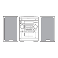
Provides instructions on how to remove the speaker front panel.
Provides instructions on how to attach the speaker front panel.
Lists the parts that constitute the speaker system.
Lists included accessories and package contents.
| Brand | Aiwa |
|---|---|
| Model | NSX-VC38 |
| Category | Stereo System |
| Language | English |