Do you have a question about the Aiwa nsx-vc58 hc and is the answer not in the manual?
Power output and distortion specifications for the mid-high and low frequency amplifiers.
Specifications for the CD player, including laser, D-A converter, and signal-to-noise ratio.
General specifications covering power requirements, consumption, dimensions, and weight.
Specific precautions and procedures for safely replacing the optical block, including static discharge.
Step-by-step guide for adjusting the MW VT (Voltage Tuning) using test points and inductors.
| Brand | Aiwa |
|---|---|
| Model | NSX-VC58 HC |
| Category | Stereo System |
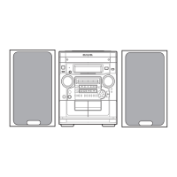
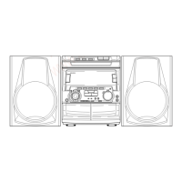
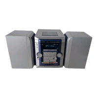
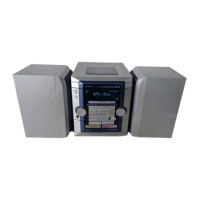
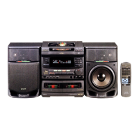
| Type | Mini Hi-Fi System |
| CD Player | Yes |
| Remote Control | Yes |
| Functions | CD, Radio, Cassette |
| Cassette Deck | Yes |
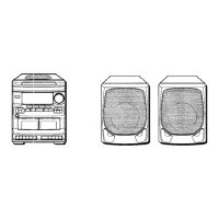
| Speakers | 2 speakers |