EasyManua.ls Logo

Aiwa NSX-VC720 User Manual

Aiwa NSX-VC720
35 pages
To Next Page IconTo Next Page
Page #1 background imageLoading...
Page #1 background image
SERVICE MANUAL
DATA
COMPACT DISC
STEREO SYSTEM
BASIC TAPE MECHANISM : 2ZM-3MK2 PR9NM
BASIC CD MECHANISM : BZG-5 MVSD3NM
NSX-VC720
HR
S/M Code No. 09-01B-450-0R1
 This Service Manual is the Revision Publishing and replaces
Simple Manual of NSX-VC720 <HR>, (S/M Code No. 09-01A-450-0T1).
 If requiring information about the CD mechanism, see Service Manual of
BZG-5, (S/M Code No. 09-00C-353-3N8).
REVISION
NSX-VC720
SPEAKERSYSTEM
CX-NVC720
RC-BAS07 VS
CD
CASSEIVER
REMOTE
CONTROLLER
SX-WNSZ700
SX-R290
(OPTIONAL)
w
w
w
.
x
i
a
o
y
u
1
6
3
.
c
o
m
Q
Q
3
7
6
3
1
5
1
5
0
9
9
2
8
9
4
2
9
8
T
E
L
1
3
9
4
2
2
9
6
5
1
3
9
9
2
8
9
4
2
9
8
0
5
1
5
1
3
6
7
3
Q
Q
TEL 13942296513 QQ 376315150 892498299
http://www.xiaoyu163.com
Question and Answer IconNeed help?

Do you have a question about the Aiwa NSX-VC720 and is the answer not in the manual?

Aiwa NSX-VC720 Specifications

General IconGeneral
TypeStereo System
CD PlayerYes
Cassette DeckYes
Speakers2
Dimensions430 x 275 x 290 mm
Remote controlYes
Radio TunerAM/FM
FunctionsCD, Radio, Cassette

Summary

Specifications

General

General technical specifications for the device.

Main Unit CX-NVC720

Technical specifications for the main unit.

Front Speakers SX-WNSZ700

Technical specifications for front speakers.

Surround Speakers SX-R290 (Optional)

Technical specifications for optional surround speakers.

Protection of Eyes from Laser Beam During Servicing

Precaution to Replace Optical Block (KSS-213F)

Precautions for replacing the optical block, including ESD.

Note on Before Starting Repair

Forced Discharge of Electrolytic Capacitor

Procedure to safely discharge power supply capacitors before repair.

Microcomputer Exchange Pre-checks

Checks before replacing the microcomputer, including HOLD terminal status, reset, and soldering.

Electrical Main Parts List

Chip Resistor Part Code

Explanation of chip resistor part coding and dimensions.

Transistor Illustration

Visual representations and pinouts of various transistors.

Wiring-1 (Main C.B)

Schematic Diagram–1 (Main 1/2; Amp Section / Head)

Schematic Diagram–2 (Main 2/2; Tuner Section)

Schematic Diagram–3 (Fan)

Wiring-2 (Front/Motor/Box SW)

Wiring-3 (M-Op-Panel/S-Op-Panel)

Schematic Diagram–4 (Front / Motor / Box SW / M-Op-Panel / S-Op-Panel / Deck)

Wiring-4 (PT)

Schematic Diagram–5 (PT)

Wiring-5 (Deck/Head-1 / Head-2)

IC Block Diagram

FL (BJ815GNK) Grid Assignment and Anode Connection

Grid Assignment

Diagram showing grid assignments for the FL display.

Anode Connection

Details of anode connections for the FL display segments.

IC Description

Adjustment <Tuner / Deck / Front >

Tuner Section Adjustments

Procedures for adjusting tuner frequency, VT, tracking, and AM IF.

Deck Section Adjustments

Procedures for tape speed, head azimuth, and frequency response adjustments.

Front Section Adjustments

Procedure for clock adjustment in the front section.

CD Test Mode

Starting the CD Test Mode

Instructions on how to activate the CD test mode.

Exiting the CD Test Mode

Instructions on how to deactivate the CD test mode.

CD Test Mode Functions

Description of functions and their checking items within the CD test mode.

Mechanical Exploded View 1/1

Mechanical Parts List 1/1

Color Name Table

Table correlating color symbols with their names and appearances.

Tape Mechanism Exploded View 1/1

Tape Mechanism Parts List 1/1

General Speaker Disassembly Instructions (For Reference)

Speaker Panel Removal

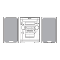
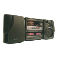
Step-by-step guide for removing the front speaker panel.

Speaker Panel Attachment

Step-by-step guide for attaching the front speaker panel.
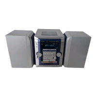
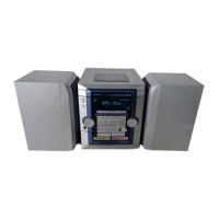
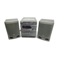
Speaker Parts List <SX – WNSZ700 (YJ3SL, YJSL, Y1SL)>

Speaker Parts List <SX – R290 (YSC,YJSC,YUSC)>

Accessories / Package List

Related product manuals