Do you have a question about the Aiwa NSX-V900 and is the answer not in the manual?
Details on the FM tuner's range, sensitivity, and antenna.
Details on the MW tuner's range, sensitivity, and antenna.
Details on the LW tuner's range, sensitivity, and antenna.
Specifications for power output, harmonic distortion, inputs, and outputs.
Specifications for track format, frequency response, and heads.
Specifications for laser, D-A converter, S/N ratio, and distortion.
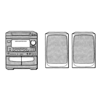
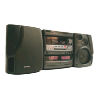
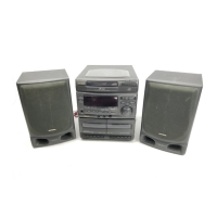
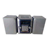
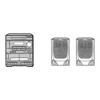
Specifications for the SX-ANV900 speaker system.
Overall specifications including power requirements and dimensions.
Crucial safety guidelines for handling laser components during servicing.
Diagram showing the grid assignment for the FL display.
Diagram showing the anode connection for the FL display.
Detailed pinout and function description for IC LC866448V-5B18.
Detailed pinout and function description for IC TC4052BP.
Detailed pinout and function description for IC LC72131.
Step-by-step procedures for adjusting the tuner section.
Procedures for adjusting tape speed, azimuth, and frequency response.
Practical figures and performance data for the tuner section.
| Brand | Aiwa |
|---|---|
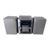
| Model | NSX-V900 |
| Category | Stereo System |
| Language | English |