EasyManua.ls Logo

Aiwa NSX-V929 User Manual

Aiwa NSX-V929
35 pages
To Next Page IconTo Next Page
Page #1 background imageLoading...
Page #1 background image
Question and Answer IconNeed help?

Do you have a question about the Aiwa NSX-V929 and is the answer not in the manual?

Aiwa NSX-V929 Specifications

General IconGeneral
BrandAiwa
ModelNSX-V929
CategoryStereo System
LanguageEnglish

Summary

Product Overview

Model Identification and Basic Specifications

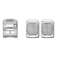
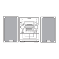
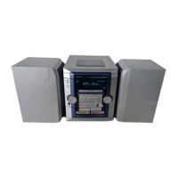
Identifies NSX-V900/V929 models, lists basic mechanisms and system configurations.

Detailed System Specifications

Tuner, Amplifier, and Cassette Deck Specs

Details specifications for tuner, amplifier, and cassette deck sections.

CD Player, Speaker, and General Specs

Covers CD player, speaker system, general unit dimensions, and power requirements.

Safety Precautions

Laser Safety and Optical Block Handling

Provides crucial safety instructions for laser beams and optical block replacement.

Tuner Block Diagram

Tuner Section Signal Flow

Illustrates the block diagram of the tuner section, showing major components and signal flow.

Main and Front Circuit Block Diagrams

Main C.B Block Diagram (Part 1/2)

Details the block diagram for the Main Circuit Board (Part 1).

Front C.B Block Diagram

Details the block diagram for the Front Circuit Board.

Main Circuit Board Wiring Diagrams

Main Circuit Board Wiring Diagrams (Continued)

Main C.B Wiring Diagram (Part 1)

Illustrates the wiring connections on the Main Circuit Board (Part 1).

Main Circuit Board Wiring Details

Schematic Diagrams

Tuner Section Schematic

Presents the schematic diagram for the tuner section.

Schematic Diagrams (Continued)

Main Circuit Board Schematic

Provides the schematic diagram for the Main Circuit Board.

IC Pin Descriptions

IC Pin Descriptions (Continued)

Adjustment Procedures - Tuner and Deck

Tuner Section Adjustments

Provides adjustment procedures for the tuner section, including clock and VT checks.

Deck Section Adjustments

Details adjustment procedures for the deck section, including tape speed and azimuth.

Adjustment Procedures - Tuner and Deck (Continued)

Tuner FM/MW Adjustments

Covers FM tracking, DC balance, mono distortion, and auto stop level adjustments.

Deck Frequency Response and Sensitivity Adjustments

Details frequency response and sensitivity adjustments for the deck.

Practical Service Performance Figures

Mechanical Parts Information

Main Unit Mechanical Assembly

Shows the exploded view of the main unit, identifying mechanical parts.

Tape Mechanism Exploded View

Tape Mechanism Assembly (View 1)

Shows the exploded view of the tape mechanism assembly.

Tape Mechanism Exploded View (Continued)

Tape Mechanism Assembly (View 2)

Provides a second view of the tape mechanism assembly and its parts.

Spring Application Positions

Related product manuals