Do you have a question about the Aiwa RC-CAS06 and is the answer not in the manual?
Tuner specifications including FM/MW/LW ranges and sensitivity.
Amplifier power output and input/output details.
Cassette deck specifications: format, response, system, heads.
CD player specifications: laser, converter, S/N ratio, wow/flutter.
General specifications: power, dimensions, weight.
Speaker system specifications: units, impedance, dimensions, weight.
List of electrical components specific to the CX-LEM50 model.
List of electrical components specific to the CX-LEM57 model.
Electrical components list for the CZA-3 model.
Electrical components list for the 3ZG-3 unit.
Electrical components list for the 3ZG-2 unit.
Component layout on the main circuit board (component side).
Component layout on the main circuit board (conductor side).
Schematic of the main circuit board and its connections.
Schematic of the key input circuit board (part 1/2).
Component layout on the front circuit board (component side).
Component layout on the front circuit board (conductor side).
Schematic of the front circuit board and its connections.
Schematic of the deck mechanism circuit board.
Component layout on the CD circuit board (component side).
Component layout on the CD circuit board (conductor side).
Schematic of the CD circuit board and its connections.
Schematic of the drive mechanism circuit board.
Schematic of the load mechanism circuit board.
Wiring diagram for the tuner circuit board.
Schematic of the tuner circuit board and its connections.
Wiring diagram for the power transformer (PT) circuit board.
Schematic of the power transformer (PT) circuit board.
Component layout on the key input circuit board (component side).
Component layout on the key input circuit board (conductor side).
Schematic of the key input circuit board.
Wiring diagram for the load mechanism circuit board.
Wiring diagram for the deck mechanism circuit board.
Wiring diagram for the drive mechanism circuit board.
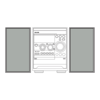
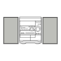
Diagram showing the physical breakdown and assembly of the unit's components.
List of mechanical parts specific to the CX-LEM50 model.
List of mechanical parts specific to the CX-LEM57 model.
List of speaker parts for the SX-LEM50 model.
List of speaker parts for the SX-LEM57 model.
List of accessories for CX-LEM50 and CX-LEM57 models.
Additional parts list for CX-LEM50 and CX-LEM57 models.
Additional parts list for the CZA-3 unit.
Additional parts list for the 3ZG-3 unit.
| Brand | Aiwa |
|---|---|
| Model | RC-CAS06 |
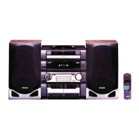
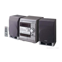
| Category | Stereo System |
| Language | English |