EasyManua.ls Logo

Aiwa RC-ZAS01 User Manual

Aiwa RC-ZAS01
37 pages
To Next Page IconTo Next Page
Page #1 background imageLoading...
Page #1 background image
SERVICE MANUAL
DATA
COMPACT DISC STEREO
CASSETTE RECEIVER
NSX-SZ70
NSX-SZ72
NSX-SZ73
EZ,K
EZ
EZ
S/M Code No. 09-006-425-3R3
REVISION
BASIC TAPE MECHANISM: 2ZM-3MK2 PR4NM
BASIC CD MECHANISM: AZG-1 ZD3RDM
This Service Manual is the “Revision Publishing” and replaces “Simple Manual”
NSX-SZ70/SZ72/SZ73 (S/M Code No. 09-002-425-3T3).
If requiring information about the CD mechanisim, see Service Manual of AZG-1
(S/M Code No. 09-001-335-3N8).
CD-CASSEIVER
CX-NSZ70
CX-NSZ72
CX-NSZ73
SPEAKER
SX-WNSZ70
SX-WNSZ71
SX-WNH81
SYSTEM
NSX-SZ70
NSX-SZ72
NSX-SZ73
REMOTE CONTROLLER
RC-ZAS01
All manuals and user guides at all-guides.com
all-guides.com
Question and Answer IconNeed help?

Do you have a question about the Aiwa RC-ZAS01 and is the answer not in the manual?

Aiwa RC-ZAS01 Specifications

General IconGeneral
CD PlayerYes
Cassette Player/DeckYes
Radio/TunerFM/AM
Remote ControlYes
Power SourceAC / Battery

Summary

Aiwa Service Manual Overview

Product Identification and Core Components

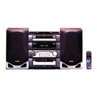
Lists supported NSX-SZ models and their basic tape/CD mechanisms.

Aiwa NSX-SZ Series Specifications

Amplifier Performance Details

Covers power output, distortion, inputs, and outputs for the amplifier.

Laser Safety During Servicing

Critical Laser Exposure Warnings

Essential safety warnings regarding laser beam exposure risks.

Pre-Repair Safety and Checks

Capacitor Discharge Procedure

Method for safely discharging power supply capacitors before repair.

Microcomputer Pre-Replacement Verification

Steps to confirm microcomputer malfunction before replacement.

Microcomputer Troubleshooting Steps

Forced Microcomputer Reset Method

Procedure to perform a hard reset on the microcomputer.

Component Identification and Illustrations

Circuit Diagrams and Wiring Layouts

Main Circuit Board Wiring Diagram

Illustrates the physical wiring connections on the main board.

Integrated Circuit Block Diagrams

Key IC Functional Block Diagrams

Illustrates the internal functions of major ICs.

Front Panel Display (FL) Information

Integrated Circuit Pin Descriptions

LC876564V Series IC Pinout Details

Comprehensive pin function descriptions for the LC876564V series.

Service Test Procedures

Tuner Section Testing and Adjustment

Steps for verifying and calibrating tuner circuit performance.

Tape Deck Performance Testing

Procedures for checking and adjusting tape speed, azimuth, and frequency response.

Tape Mechanism Exploded View

Speaker Unit Servicing

Related product manuals