EasyManua.ls Logo

Aiwa SIMPLE-2 XH-AG1000 HR User Manual

Aiwa SIMPLE-2 XH-AG1000 HR
57 pages
To Next Page IconTo Next Page
Page #1 background imageLoading...
Page #1 background image
SERVICE MANUAL
DATA
COMPACT DISC
STEREO SYSTEM
BASIC TAPE MECHANISM : 6ZM-1 AR3NM
BASIC CD MECHANISM : AZG-1 VZD3RNDM
XH-AG1000
HR
S/M Code No. 09-007-431-8R1
REVISION
• This Service Manual is the “Revision Publishing” and replaces “Simple Manual”
XH-AG1000 (HR), (S/M Code No. 09-005-431-8T1).
• This Service Manual does not include “CD TEST MODE”. This item will be
issued in the next supplement.
If requiring information about the CD mechanism, see Service Manual of AZG-1
(S/M Code No. 09-001-335-3NG).
XH–AG1000 RC–AAS01
SYSTEM
CD
SPEAKERS
REMOTE
CX–AG1000
SX–WA1000
SX-C1800
SX–R1800
SIMPLE-2
Apartofcontentsisadequate.
Re-issuing is under request.

Table of Contents

Question and Answer IconNeed help?

Do you have a question about the Aiwa SIMPLE-2 XH-AG1000 HR and is the answer not in the manual?

Aiwa SIMPLE-2 XH-AG1000 HR Specifications

General IconGeneral
BrandAiwa
ModelSIMPLE-2 XH-AG1000 HR
CategoryStereo System
CD PlayerYes
USB PlaybackYes
FM TunerYes
Speaker Configuration2.0

Summary

SPECIFICATIONS

Product Specifications

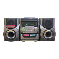
Detailed technical specifications for the main unit and speaker systems.

SAFETY PRECAUTIONS

Laser Beam Safety Guidelines

Crucial safety warnings for handling laser components during servicing.

REPAIR PREPARATION

Capacitor Discharge and Microcomputer Checks

Procedures for safely discharging capacitors and verifying microcomputer function before repair.

DISASSEMBLY INSTRUCTIONS

CD Unit Disassembly

Step-by-step instructions for disassembling the CD mechanism.

ELECTRICAL MAIN PARTS LIST

Component Listings

Comprehensive lists of electrical components including ICs, transistors, capacitors, and resistors.

CHIP RESISTOR CODING SYSTEM

Resistor Part Code Explanation

Explanation of the part coding system for chip resistors.

TRANSISTOR ILLUSTRATIONS

Transistor Pinout Diagrams

Visual guide to transistor pin configurations.

WIRING DIAGRAMS

System Wiring Diagrams

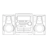
Wiring diagrams for main unit, front panel, circuit boards, and system connections.

SCHEMATIC DIAGRAMS

System Schematics

Schematics for main unit, circuit boards, tuner, and power supply sections.

FL DISPLAY GRID ASSIGNMENTS

Display Grid Layouts

Grid assignment and anode connection details for FL displays.

INTEGRATED CIRCUIT (IC) INFORMATION

IC Block Diagrams and Descriptions

Visual diagrams and detailed descriptions of IC functions and pinouts.

ADJUSTMENT PROCEDURES

Deck and Tuner Adjustments

Procedures for adjusting deck speed, azimuth, and tuner functions.

MECHANICAL INFORMATION

Exploded Views and Parts Lists

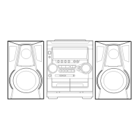
Mechanical exploded views and parts lists for the main unit and tape mechanism.

SPEAKER INFORMATION

Speaker Disassembly and Parts Lists

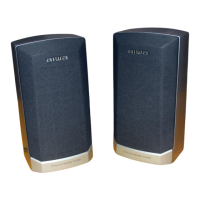
Instructions for speaker disassembly and parts lists.

ACCESSORIES AND PACKAGE LIST

Included Accessories and Packaging

List of accessories and packaging contents.

Related product manuals