EasyManua.ls Logo

Aiwa SX-S80 User Manual

Aiwa SX-S80
42 pages
To Next Page IconTo Next Page
Page #1 background imageLoading...
Page #1 background image
SERVICE MANUAL
DATA
COMPACT DISC STEREO
CASSETTE RECEIVER
BASIC TAPE MECHANISM : 2ZM-3MK2 PR7NM
BASIC CD MECHANISM : AZG-1 VZD3RNDM
NSX-VC88
HR
S/M Code No. 09-005-428-7R1
REVISION
This Service Manual is the "Revision Publishing" and replaces "Simple Manual"
NSX-VC88 (HR), (S/M Code No. 09-005-428-7T1).
If requiring information about the CD mechanism, see Service Manual of
AZG-1 VZD3RNDM, (S/M Code No. 09-001-335-3NG).
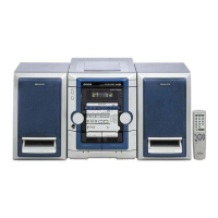
NSX–VC88
MAIN
SPEAKER
SYSTEM
CD
CASSEIVER
REMOTE
CONTROLLER
RC–ZAS07CX–NVC88 SX–WNSZ85
SATELLITE
SPEAKER
SX–S80
Question and Answer IconNeed help?

Do you have a question about the Aiwa SX-S80 and is the answer not in the manual?

Aiwa SX-S80 Specifications

General IconGeneral
CD PlayerYes
EqualizerYes
Cassette DeckYes
TunerAM/FM
OutputsHeadphones

Summary

Product Specifications

FM/AM Tuner Specifications

Tuning range, sensitivity, and antenna terminals for FM and AM reception.

Amplifier Specifications

Power output, total harmonic distortion, and input/output levels for the audio amplifier.

Cassette Deck Specifications

Details on track format, frequency response, and recording/playback heads.

CD Player Specifications

Laser type, D-A converter, signal-to-noise ratio, and power requirements for CD playback.

Speaker System Specifications

Information on speaker impedance, units, and output sound pressure levels.

Servicing Safety Precautions

Laser Beam Safety During Servicing

Essential safety measures and warnings for handling laser components during maintenance.

Optical Block Replacement Precautions

Guidelines for preventing damage from electrostatic discharge during optical block replacement.

Repair Procedures and Notes

Pre-Repair Safety: Capacitor Discharge

Step-by-step procedure to safely discharge capacitors before starting repair work.

Microcomputer Troubleshooting Checks

Key checks, including HOLD terminal status and reset procedures, for diagnosing microcomputer faults.

IC Block Diagrams

IC M65849BFP631D Block Diagram

Functional overview and pin assignments for the M65849BFP631D integrated circuit.

IC BU2099FV Block Diagram

Internal logic and pin functions for the BU2099FV integrated circuit.

Adjustments and Calibration

Tuner Section Adjustments

Procedures for adjusting clock frequency, AM/FM VT, and tracking for tuner performance.

Deck Section Adjustments

Calibration steps for tape speed, head azimuth, and frequency response.

Front Section Calibration

Instructions for performing the µ-CON OSC adjustment for front panel functionality.

Mechanical Information

Exploded Views

Diagrams illustrating the assembly of main unit and tape mechanism components.

Speaker Disassembly Instructions

Step-by-step guide for safely disassembling various speaker types.

Related product manuals