Do you have a question about the Aiwa XR-M99 and is the answer not in the manual?
Technical specifications for the integrated amplifier model.
Technical specifications for the stereo tuner model.
Technical specifications for the stereo cassette deck model.
Technical specifications for the mini disc recorder model.
Technical specifications for the compact disc player model.
Technical specifications for the speaker system model.
Detailed pinout and function description for the LC72131D IC.
Detailed pinout and function description for the LC876580W-5M70 IC.
Detailed pinout and function description for the LC78622ED IC.
Detailed pinout and function description for the LA9241ML IC.
Detailed pinout and function description for the LC78622ED IC.
Detailed pinout and function description for the LA9241ML IC.
Detailed pinout and function description for the BU4094BCF IC.
Detailed pinout and function description for the BA5936 IC.
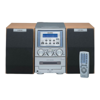
| Brand | Aiwa |
|---|---|
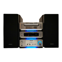
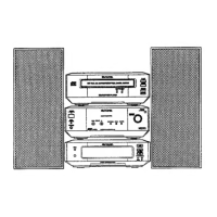
| Model | XR-M99 |
| Category | Stereo System |
| Language | English |