Do you have a question about the Aiwa XR-M36 and is the answer not in the manual?
Critical safety warnings and precautions to prevent damage.
Precautions for replacing the optical pickup block to prevent static discharge damage.
Procedures for removing the top cabinet and CD section.
Procedures for removing the top cabinet and CD section.
Pin configuration and functions for M38B57MC-P218FP/M38B57MCH-P226F IC.
Pin configuration and functions for LA9241ML IC.
Continued pin configuration and functions for LA9241ML IC.
Continued pin configuration and functions for LA9241ML IC.
Pin configuration and functions for M38B57MC-P218FP/M38B57MCH-P226F IC.
Continued pin configuration and functions for M38B57MC-P218FP/M38B57MCH-P226F IC.
Pin configuration and functions for LC72131D IC.
Continued pin configuration and functions for LC72131D IC.
Continued pin configuration and functions for LC72131D IC.
Checks for clock frequency, AM/FM/LW VT, tracking, and IF.
Procedures for FM tracking, separation, DC balance, and distortion adjustments.
Procedures for adjusting tape speed and head azimuth.
Procedures for checking playback and record/playback frequency response.
Specifications for tuner (FM, AM, LW) and deck sections.
Lists of capacitors, connectors, diodes, ferrite beads, ICs, pins, protectors, transistors, and wires.
Lists of capacitors, diodes, ICs, coils, and transistors.
Lists of capacitors, connectors, diodes, ferrite beads, ICs, pins, protectors, transistors, and wires.
Lists of capacitors, diodes, ICs, protectors, and transistors.
Lists of capacitors, connectors, diodes, ICs, coils, and transistors.
Lists of capacitors, diodes, ICs, coils, and transistors.
Lists of capacitors, diodes, ICs, pins, protectors, PT, relays, and terminals.
Lists of cabinets, panels, keys, springs, FF cables, and PT parts.
Lists of capacitors, connectors, diodes, ferrite beads, ICs, pins, protectors, transistors, and wires.
Lists of capacitors, diodes, ICs, coils, and transistors.
Lists of capacitors, connectors, diodes, ferrite beads, ICs, pins, protectors, transistors, and wires.
Lists of capacitors, diodes, ICs, protectors, and transistors.
Lists of capacitors, connectors, diodes, ICs, coils, and transistors.
Lists of capacitors, diodes, ICs, coils, and transistors.
Lists of capacitors, diodes, ICs, pins, protectors, PT, relays, and terminals.
Lists of cabinets, panels, keys, springs, FF cables, and PT parts.
| Brand | Aiwa |
|---|---|
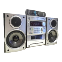
| Model | XR-M36 |
| Category | Stereo System |
| Language | English |