Do you have a question about the Aiwa XR-M34 and is the answer not in the manual?
Details FM, AM, and Timer specifications for the D model.
Details the power output specifications for the D model.
Details tape format and frequency response for the D model.
Details CD disc format, read method, and wow/flutter for the D model.
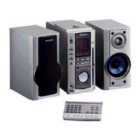
Details speaker format, impedance, and input for the D model.
Tuning range and usable sensitivity for FM tuners.
Tuning range and usable sensitivity for MW tuners.
Tuning range and usable sensitivity for AM tuners.
Tuning range and usable sensitivity for LW tuners.
Power output details for various models.
Track format and frequency response.
Laser, D-A converter, and signal-to-noise ratio details.
Power requirements and consumption.
Cabinet type, speaker details, impedance, and output sound pressure.
Critical safety warnings regarding fire, shock, and injury.
Warnings about potential damage or minor injury from incorrect handling.
Do not approach laser exit with eye too close. Observe from distance.
Improper procedures may result in hazardous radiation exposure.
Electrostatic discharge can damage laser diode. Ground yourself.
Steps to remove the top cabinet using screws and sliding.
Steps to remove the CD unit using screws and disconnections.
Steps to remove the top cabinet.
Steps to remove the CD section.
Shows grid assignment for FL display segments.
Details anode connections for FL display segments.
Lists pin numbers and their corresponding connections.
Check clock frequency using test points and specific frequencies.
Check AM voltage (VT) at test points under specific conditions.
Adjust AM tracking using test points and potentiometer.
Adjust AM intermediate frequency (IF) using test points.
Check FM voltage (VT) at test points under specific conditions.
Check FM tracking using test points and signal level.
Adjust DC balance and check mono distortion.
Check AM separation by adjusting potentiometer.
Check FM separation using test points and signal level.
Check clock frequency for HE, HR, LH, EZ, K models.
Check AM (MW) VT for HE, HR, LH, EZ, K models.
Adjust AM (MW) tracking for HE, HR, LH, EZ, K models.
Adjust AM (MW) IF for HE, HR, LH, EZ, K models.
Check LW VT for EZ, K models.
Adjust LW tracking for EZ, K models.
Check FM VT for HE, HR, LH, EZ, K models.
Check FM tracking for HE, HR, LH, EZ, K models.
Adjust DC balance and check distortion.
Check FM separation for HE, HR, LH, EZ, K models.
Adjust tape speed using test tape and frequency counter.
Adjust head azimuth using test tape and adjustment screw.
Check playback frequency response using test tape.
Check record/playback frequency response.
Service figures for FM sensitivity, S/N, distortion, separation.
Service figures for AM sensitivity, S/N, distortion, separation.
Service figures for LW sensitivity, S/N.
Service figures for tape speed, wow/flutter, torque, tension, distortion, noise.
| Brand | Aiwa |
|---|---|
| Model | XR-M34 |
| Category | Stereo System |
| Language | English |