EasyManua.ls Logo

Aiwa XR-M11 User Manual

Aiwa XR-M11
78 pages
To Next Page IconTo Next Page
Page #1 background imageLoading...
Page #1 background image
alwdwa
XR-M11
XR-M12
XR-M22
XR-M33
XR-M34
XR-M36
¢
BASIC
TAPE
MECHANISM
:
2ZM-1
R8NM
/
YR8NM
/
YR8NC
*
BASIC
CD
MECHANISM
:
3ZG-3
E3NM
/
YE3NM
/
E2NC
COMPACT
DISC
STEREO
SYSTEM
fi,
2,-1—
K
1
8ZCL7-0133
(S)
8ZCL7-0137
(S)
XR-M14
XR-M11
Se
1
YR8NC|
3ZG-3
E2NC
XR-M12
ez
XR-M22
HR,
LH
__|2ZM-1
YR8NC|
3ZG-3
E2NC
XR-M33
XR-M34
2ZM-1
R8NM
|
3ZG-3
E3NM
XR-M36
S/M
Code
No.
09-996-—400—3R2
XR-M22.
|
HE
__|2ZM—1
YR8NM|3ZG-3
YE3NM|_RC-ZAT04
ana
SERVICE
¢
TYPE:
D,HE,HR,
LH,EZ,K
TAPE
cD
REMOTE
Sie
SEN
aie
MECHANISM
|
MECHANISM
CONTROLLER
[RC-ZAT03(VS)|
RC-ZATO04(VS)
RC-—ZAT04(VS
RC-ZAT04
ie]
=
Zz
—<
=
<2
QO
_—
_—
rH
[1
Sr
Question and Answer IconNeed help?

Do you have a question about the Aiwa XR-M11 and is the answer not in the manual?

Aiwa XR-M11 Specifications

General IconGeneral
CD PlayerYes
Remote ControlYes
Power Output20W per channel
Radio TunerYes
Cassette DeckYes
SpeakersYes
Tuner BandsAM/FM
Output Power20W per channel
Tape DeckYes
Frequency Response20Hz - 20kHz
Signal-to-Noise Ratio80dB
Weight5.5 kg
Power SupplyAC power
TypeMini Hi-Fi System

Summary

Aiwa XR-M11/XR-M12 Service Manual

System Overview

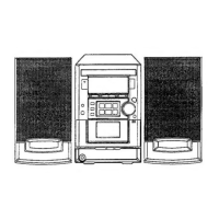
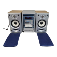
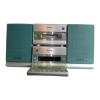
General information about the Compact Disc Stereo System.

Specifications - Type D Models

Tuner, Timer, Amplifier Specs

Detailed specifications for tuner, timer, and amplifier sections.

Cassette Deck and CD Player Specs

Specifications for cassette deck and CD player mechanisms.

Common and Speaker Specs

General unit specifications and speaker details.

Specifications - Types HE, HR, LH, EZ, K

Tuner Section Specifications (FM/MW/AM/LW)

FM, MW, AM, and LW tuner specifications for various types.

Amplifier, Cassette, CD Player Specs

Power output, cassette, and CD player details for different types.

General Unit and Speaker Specifications

Overall unit specifications and speaker system details.

Safety Precautions for Servicing

Warning: Critical Safety Procedures

Essential warnings regarding parts, electrical safety, and handling.

Caution: General Service Guidelines

General cautions for safe servicing and proper reassembly.

Laser Handling Precautions

Specific safety measures when working with laser components.

Laser Beam Eye Safety

Warning: Avoiding Laser Exposure

Critical warnings about eye exposure to laser radiation.

Optical Block Replacement Precautions

Handling instructions for optical block to prevent electrostatic damage.

Disassembly Instructions - Type D

Top Cabinet Removal Steps

Procedure for removing the top cabinet.

CD Section Removal Steps

Steps for removing the CD mechanism.

Disassembly Instructions - Types HE, HR, LH, EZ, K

Top Cabinet Removal Procedure

Steps to remove the top cabinet for specific models.

CD Section Removal Procedure

Guide for detaching the CD section.

Electrical Main Parts List (Part 1)

Integrated Circuits (IC) Listings

Part numbers and descriptions for ICs.

Transistors Listings

Part numbers and descriptions for transistors.

Diodes Listings

Part numbers and descriptions for diodes.

Electrical Main Parts List (Part 2)

Capacitors (C Series) - Part 1

List of capacitors with part numbers.

Electrical Main Parts List (Part 3)

Capacitors (C Series) - Part 2 & Connectors

Further capacitor listings and connector parts.

LEDs and Switches

Part numbers for LEDs and switches.

Electrical Main Parts List (Part 4)

Capacitors (C Series) - Part 3 & Relays

Additional capacitor and relay part details.

Deck Control Board Components

Components specific to the deck control board.

Electrical Main Parts List (Part 5)

Connectors, Fuses, Jacks, and Coils

Part details for connectors, fuses, jacks, and coils.

Chip Resistor Coding System

Explanation of the chip resistor part coding.

Transistor Illustrations

Common Transistor Pinouts

Visual guide to common transistor pin configurations.

Specific Transistor Identification

Illustrations for specific transistor models.

Block Diagrams

System Block Diagram 1

High-level block diagram of main system sections.

System Block Diagram 2

High-level block diagram of CD player sections.

Schematic Diagrams - Main & Relay

Schematic Diagram 1 (Main 1/2, Relay)

Detailed circuit for main board (1/2) and relay board.

IC Block Diagrams

IC M62495FP, TA2092N, LC72131D Diagrams

Functional block diagrams for specific ICs.

IC Block Diagrams - Specific ICs

IC BU1920FS, LA1837NL Diagrams

Functional block diagrams for BU1920FS and LA1837NL ICs.

Schematic Diagrams - Tuner Section (Type D)

Schematic Diagram 2 (Main 2/2: Tuner)

Detailed circuit for the tuner section of the main board.

Wiring Diagrams - Main Board (Type D)

Wiring 1 (Main) for D, HE, HR, LH

Wiring diagram for the main board covering specific types.

Schematic Diagrams - Tuner Section (Type EZ, K)

Schematic Diagram 3 (Main 2/2: Tuner)

Detailed circuit for the tuner section of the main board for EZ, K types.

Wiring Diagrams - Main Board (Type EZ, K)

Wiring 2 (Main) for EZ, K

Wiring diagram for the main board covering EZ and K types.

Schematic Diagrams - Front & Deck Sections

Schematic Diagram 4 (Front/Deck)

Detailed circuit for the front and deck sections.

Wiring Diagrams - Front, Deck & Relay

Wiring 3 (Front/Deck/Relay)

Wiring diagram covering front, deck, and relay sections.

Schematic Diagrams - CD Sections

Schematic Diagram 5 (CD/CD Load/Drive)

Detailed circuit for CD, CD Load, and CD Drive sections.

Wiring Diagrams - CD Sections

Wiring 4 (CD/CD Load/Drive)

Wiring diagram for CD, CD Load, and CD Drive sections.

Schematic Diagrams - PT Section

Schematic Diagram 6 (PT) - EZ, K Only

Detailed circuit for the PT section for EZ and K types.

Schematic Diagram 6 (PT) - LH, HE, HR Only

Detailed circuit for the PT section for LH, HE, HR types.

Wiring Diagrams - PT Section

Wiring 5 (PT) - EZ, K Only

Wiring diagram for the PT section for EZ and K types.

Wiring 5 (PT) - LH, HE, HR Only

Wiring diagram for the PT section for LH, HE, HR types.

FL Display Connections

FL Grid Assignment

Grid assignments for the FL display.

FL Anode and Pin Connections

Anode and pin connection details for the FL display.

IC Descriptions - Type D

IC M38B57MC/M38B57MCH Pinout

Pin functions for the M38B57MC/M38B57MCH IC.

IC Descriptions - Type D (Continued)

IC M38B57MC/M38B57MCH Pinout (Continued)

Further pin functions for the M38B57MC/M38B57MCH IC.

IC Descriptions - Types HE, HR, LH, EZ, K

IC M38B57MC/M38B57MCH Pinout (HE/HR/LH/EZ/K)

Pin functions for the M38B57MC/M38B57MCH IC for specific types.

IC Descriptions - Types HE, HR, LH, EZ, K (Continued)

IC M38B57MC/M38B57MCH Pinout (Continued 2)

Further pin functions for the M38B57MC/M38B57MCH IC.

IC Descriptions - Types HE, HR, LH, EZ, K (Continued 2)

IC LC78622ED Pinout

Pin functions for the LC78622ED IC.

IC Descriptions - Types HE, HR, LH, EZ, K (Continued 3)

IC LC78622ED Pinout (Continued)

Further pin functions for the LC78622ED IC.

IC Descriptions - Types HE, HR, LH, EZ, K (Continued 4)

IC LC72131D Pinout

Pin functions for the LC72131D IC.

IC Descriptions - Types HE, HR, LH, EZ, K (Continued 5)

IC M38B57MC/M38B57MCH Pinout (HE/HR/LH/EZ/K) - Cont.

More pin functions for the M38B57MC/M38B57MCH IC.

IC Descriptions - Types HE, HR, LH, EZ, K (Continued 6)

IC M38B57MC/M38B57MCH Pinout (Continued 2)

Additional pin functions for the M38B57MC/M38B57MCH IC.

IC Descriptions - Types HE, HR, LH, EZ, K (Continued 7)

IC LA9241ML Pinout

Pin functions for the LA9241ML IC.

IC Descriptions - Types HE, HR, LH, EZ, K (Continued 8)

IC LA9241ML Pinout (Continued)

Further pin functions for the LA9241ML IC.

IC Descriptions - Types HE, HR, LH, EZ, K (Continued 9)

IC LC78622ED Pinout (Continued 2)

More pin functions for the LC78622ED IC.

IC Descriptions - Types HE, HR, LH, EZ, K (Continued 10)

IC LC78622ED Pinout (Continued 3)

Further pin functions for the LC78622ED IC.

IC Descriptions - Types HE, HR, LH, EZ, K (Continued 11)

IC LC72131D Pinout (Continued)

Further pin functions for the LC72131D IC.

Tuner Adjustments - Type D

Clock Frequency Check Procedure

Procedure to check the clock frequency.

AM VT Check Procedure

Procedure to check the AM voltage/tuning.

AM Tracking Adjustment Procedure

Procedure for adjusting AM tracking.

AM IF Adjustment Procedure

Procedure for adjusting AM Intermediate Frequency.

FM VT Check Procedure

Procedure to check FM voltage/tuning.

FM Tracking Check Procedure

Procedure for checking FM tracking.

DC Balance & Distortion Adjustment

Procedure for adjusting DC balance and distortion.

AM Separation Check Procedure

Procedure for checking AM separation.

Tuner Adjustments - Types HE, HR, LH, EZ, K

Circuit Test Points (HE, HR, LH)

Diagram showing test points for HE, HR, LH models.

Circuit Test Points (EZ, K)

Diagram showing test points for EZ, K models.

Tuner Adjustment Procedures (HE, HR, LH, EZ, K)

Clock Frequency, AM VT, Tracking Adjustments

Procedures for clock frequency, AM VT, and tracking adjustments.

AM IF, LW VT, LW Tracking Adjustments

Procedures for AM IF, LW VT, and LW tracking adjustments.

FM VT, FM Tracking, DC Balance Adjustments

Procedures for FM VT, FM tracking, and DC balance adjustments.

FM Separation Check Procedure

Procedure for checking FM separation.

Deck Adjustments

Tape Speed Adjustment (Type D)

Procedure for adjusting tape speed.

Head Azimuth Adjustment (Type D)

Procedure for adjusting head azimuth.

Frequency Response Checks (Type D)

Procedures for checking PB and REC/PB frequency response.

Tape Speed, Azimuth, Response Adjustments (HE, HR, LH, EZ, K)

Procedures for tape speed, azimuth, and response for multiple types.

Practical Service Figures

Tuner Section Performance Specs

Key performance metrics for the tuner section.

Deck Section Performance Specs

Key performance metrics for the deck section.

Mechanical Parts List (Part 1)

Main Unit Mechanical Parts List

List of mechanical parts for the main unit.

Mechanical Parts List (Part 1) - Continued

Various Mechanical Parts List

Additional mechanical parts including badges and keys.

Tape Mechanism Exploded Views (Part 1)

Tape Mechanism Upper Assembly View

Exploded view of the upper part of the tape mechanism.

Tape Mechanism Exploded Views (Part 1) - Continued

Tape Mechanism Lower Assembly View

Exploded view of the lower part of the tape mechanism.

Tape Mechanism Parts List (Part 1)

Tape Mechanism Components List

List of parts for the tape mechanism.

Spring Application Positions

Tape Mechanism Spring Locations

Diagram showing the correct placement of springs in the tape mechanism.

CD Mechanism Exploded Views (Part 1)

CD Mechanism Upper Assembly View

Exploded view of the upper section of the CD mechanism.

CD Mechanism Parts List (Part 1)

CD Mechanism Components List (Part 1)

List of parts for the CD mechanism.

CD Mechanism Exploded Views (Part 2)

CD Mechanism Lower Assembly View

Exploded view of the lower section of the CD mechanism.

Accessories and Package List

System Accessories and Contents

List of included accessories and package contents.

Reference Name List

Electrical Component Glossary

Glossary of electrical component names.

Mechanical Component Glossary

Glossary of mechanical component names.

Manufacturer Information

AIWA CO.,LTD. Contact Details

Contact information for AIWA CO., LTD.

Simple Manual Cover

Service Manual Replacement Note

Note regarding replacing the service manual.

Electrical Main Parts List (1/7)

Capacitors and Connectors

Part numbers for capacitors and connectors.

Electrical Main Parts List (2/7)

Switches, Resistors, and Capacitors

Part numbers for switches, resistors, and capacitors.

Electrical Main Parts List (3/7)

Transistors, Diodes, and ICs

Part numbers for transistors, diodes, and ICs.

Electrical Main Parts List (4/7)

Resistors, Capacitors, and Zener Diodes

Part numbers for resistors, capacitors, and Zener diodes.

Electrical Main Parts List (5/7)

Capacitors, Coils, and ICs

Part numbers for capacitors, coils, and ICs.

Electrical Main Parts List (6/7)

Capacitors, Diodes, and Transistors

Part numbers for capacitors, diodes, and transistors.

Electrical Main Parts List (7/7)

Capacitors, ICs, and Connectors

Part numbers for capacitors, ICs, and connectors.

Related product manuals