This document is a service manual for the Aiwa XR-M120 compact disc stereo system, identified by S/M Code No. 09-009-426-2S1. It is noted as a "Supplement" that replaces the "Simple Manual" XR-M120(HC) (S/M Code No. 09-008-432-5T3). The manual also indicates that it contains information about the differences between the XR-M120(HC) and XR-M130(HR) models, and for other information, users should refer to the service manual of the XR-M130(HR) (S/M Code No. 09-007-426-2R2).
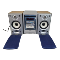
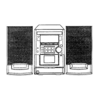
The device is a compact disc stereo system, incorporating a basic tape mechanism and a basic CD mechanism. The basic tape mechanism is specified as a 2ZM-1 R8NF, while the basic CD mechanism is a 3ZG-3 E2NF. The system comes with a remote controller, model RC-AAT11.
Technical Specifications:
FM Tuner Section:
- Tuning range: 87.5 MHz to 108 MHz
- Usable sensitivity (IHF): 13.2 dBf
- Antenna terminals: 75 ohms (unbalanced)
AM Tuner Section:
- Tuning range: 531 kHz to 1602 kHz (9 kHz step) or 530 kHz to 1710 kHz (10 kHz step)
- Usable sensitivity: 350 uV/m
- Antenna: Loop antenna
Amplifier Section:
- Power output: Rated at 8 W + 8 W (16 ohms, T.H.D. 1%, 1 kHz). Reference power is 10 W + 10 W (16 ohms, T.H.D. 10%, 1 kHz).
- Total harmonic distortion: 0.07% (7.5 W, 1 kHz, 16 ohms, DIN AUDIO)
- Inputs:
- Outputs:
- SUB WOOFER: 1.0 V
- SPEAKERS: Accepts speakers of 16 ohms or more
- PHONES (stereo minijack): Accepts headphones of 32 ohms or more
Cassette Deck Section:
- Track format: 4 tracks, 2 channels stereo
- Frequency response (Normal tape): 50 Hz – 15000 Hz
- Signal-to-noise ratio: 50 dB
- Recording system: AC bias
- Heads: Recording/Playback head x 1, Erase head x 1
Compact Disc Player Section:
- Laser: Semiconductor laser (λ = 780 nm)
- D-A converter: 1 bit dual
- Signal-to-noise ratio: 75 dB (1 kHz, 0 dB)
- Harmonic distortion: 0.1% (1 kHz, 0 dB)
- Wow and flutter: Unmeasurable
Speaker System:
- Cabinet type: 2-way, bass reflex
- Speaker:
- Woofer: 120 mm (4 3/4 in) cone type
- Tweeter: 20 mm (13/16 in) ceramic type
- Impedance: 16 ohms
- Output sound pressure level: 87 dB/W/m
- Dimensions (W x H x D): 150 x 256 x 205 mm (6 x 10 1/8 x 8 1/16 in.)
- Weight: 2.0 kg (4 lbs 7 oz)
General:
- Power requirements: AC: 120 V / 220 V - 240 V, Switchable 50/60 Hz
- Power consumption: 38 W
- Dimensions (W x H x D): 168 x 256 x 255 mm (6 5/8 x 10 1/8 x 10 1/16 in)
- Weight of main unit: 3.5 kg (7 lbs 11 oz.)
- Standby power consumption: 1.0 W (if power-economizing mode is on), 10 W (if power-economizing mode is off).
Accessories / Package List:
The system includes several accessories:
- IB, HC (CE) - FM (Part No. 8A-CLK-917-010)
- ANT, FEEDER FM (Part No. 87-043-115-010)
- ANT, LOOP AM-NC C (Part No. 87-A90-030-010)
- PLUG, CONVERSION JT-0475A (Part No. 87-A91-015-010)
- RC UNIT, RC-AAT11 (Part No. 8A-CLB-961-010)
Maintenance Features:
The manual provides detailed electrical main parts lists for various components, including ICs, transistors, diodes, and capacitors, categorized by their location on the main C.B., front C.B., CD C.B., PT C.B., and Tuner C.B. This allows for precise identification and replacement of faulty components during servicing. Wiring diagrams (Main, Tuner, Front/Relay/Deck, CD/CD Load/CD Drive, PT) and schematic diagrams (Main/Relay, Tuner, Front/Deck, CD/CD Load/CD Drive, PT) are included to guide technicians through the internal connections and circuit layouts. Mechanical exploded views for the main unit and tape mechanism are also provided, along with corresponding mechanical parts lists, to facilitate disassembly, reassembly, and replacement of mechanical components. The inclusion of a "Color Name Table" helps in identifying wiring colors for easier maintenance.