EasyManua.ls Logo

Aiwa XR-M101 - User Manual

Aiwa XR-M101
52 pages
Print Icon
To Next Page IconTo Next Page
Loading...
SERVICE MANUAL
DATA
BASIC TAPE MECHANISM : AZM-6 AR1NC
BASIC CD MECHANISM : DA11T3C
COMPACT DISC STEREO SYSTEM
XR-M101
XR-M131
S/M Code No. 09-014-355-1N1
LH(S),K(S),EZ(S)
U(S),EZ(S)
SYSTEM
XR-M101
XR-M131
CD–CASSEIVER
CX-SLM101
CX-SLM131
SPEAKER
SX-SLM101
SX-SLM131
w
w
w
.
x
i
a
o
y
u
1
6
3
.
c
o
m
Q
Q
3
7
6
3
1
5
1
5
0
9
9
2
8
9
4
2
9
8
T
E
L
1
3
9
4
2
2
9
6
5
1
3
9
9
2
8
9
4
2
9
8
0
5
1
5
1
3
6
7
3
Q
Q
TEL 13942296513 QQ 376315150 892498299
http://www.xiaoyu163.com
Question and Answer IconNeed help?

Do you have a question about the Aiwa XR-M101 and is the answer not in the manual?

Summary

Product Specifications

Main Unit Specifications

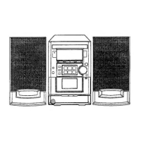
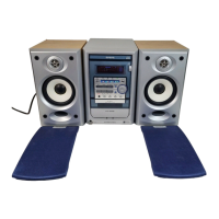
Details for tuner, amplifier, cassette deck, CD player, and speaker system.

General Specifications

Power requirements, consumption, dimensions, and overall weight.

Package Contents and Accessories

Accessory Part List

Detailed list of included accessories with part numbers.

Laser Safety During Servicing

Essential Laser Exposure Warnings

Critical safety advice to prevent eye injury from laser radiation.

Electrical Main Parts List - Part 1

IC, Transistor, and Diode Components

List of integrated circuits, transistors, and diodes for the main unit.

Electrical Main Parts List - Part 2

Capacitor Components

Detailed list of various capacitor types used in the unit.

Electrical Main Parts List - Part 3

Capacitor Components

Detailed list of various capacitor types used in the unit.

Electrical Main Parts List - Part 4

Capacitors and Connectors

List of capacitor and connector components.

Electrical Main Parts List - Part 5

Fuses, Jacks, Switches, and Coils

List of fuses, jacks, switches, and coil components.

Electrical Main Parts List - Part 6

Chip Resistor Coding and Final Components

Explanation of chip resistor coding and final component list.

Transistor Illustrations

Transistor Pinout Diagrams

Visual representations of transistor pin configurations.

Main Unit (101 LH, 131 U) Wiring Diagram

101 LH, 131 U Model Wiring

Wiring diagram for specific main unit models.

Main Unit (101 K, EZ, 131 EZ) Wiring Diagram

101 K, EZ, 131 EZ Model Wiring

Wiring diagram for specific main unit models.

Main Unit Schematic - Part 1

Main Circuit Board - Part 1;2

Schematic for the main circuit board (first part).

Main Unit Schematic - Part 2 (101 LH, 131 U)

Main Circuit Board - Part 2;2

Schematic for the main circuit board (second part).

Main Unit Schematic - Part 2 (101 K, EZ, 131 EZ)

Main Circuit Board - Part 2;2

Schematic for the main circuit board (second part).

System Sub-Assembly Wiring Diagrams

Front, Motor, CD, and Deck Board Wiring

Wiring details for various sub-assemblies like front panel, motor, etc.

Front Section Schematic Diagram

Front Circuit Board Schematic

Detailed schematic for the front section of the unit.

CD Section Schematic Diagram

CD Circuit Board Schematic

Detailed schematic for the CD player section.

Display Pinout Information

FL Display Grid and Anode Connections

Grid assignment and anode connection details for the display.

Electrical Adjustment - 101 LH, 131 U Models

101 LH, 131 U Model Adjustments

Adjustment points and procedures for specific models.

Deck Adjustment - 101 LH, 131 U Models

Tape Speed, Wow;Flutter, and Head Azimuth

Steps for adjusting tape mechanism parameters.

Tuner Adjustment - AM;FM

AM;FM VT Adjustment and DC Balance

Procedures for tuning and DC balance adjustments.

Tuner Adjustment - Tracking

Tracking Adjustment and Check

Procedures for tracking adjustments and verification.

Electrical Adjustment - 101 K, EZ, 131 EZ Models

101 K, EZ, 131 EZ Model Adjustments

Adjustment points and procedures for specific models.

Deck Adjustment - 101 K, EZ, 131 EZ Models

Tape Speed, Wow;Flutter, and Head Azimuth

Steps for adjusting tape mechanism parameters.

Tuner Adjustment - LW;MW;FM

LW;MW;FM VT Adjustment and DC Balance

Procedures for tuning and DC balance.

Tuner Adjustment - IF;Tracking MW;LW

IF and Tracking Adjustments

Procedures for IF and tracking adjustments for MW/LW.

Tuner Adjustment - FM Tracking Check

FM Tracking Check

Procedure for checking FM tracking.

CD Adjustment - Focus & RF Waveform

Focus Bias and RF Waveform Check

Procedures for CD player focus and RF signal checks.

CD Adjustment - Jitter, Playability & Laser Current

Jitter, Playability, and Laser Current Checks

Procedures for CD player jitter, playback, and laser checks.

CD Test Mode Operations

Starting, Exiting, and Using CD Test Mode

Instructions for operating the CD test mode.

IC Block Diagrams - BU1920 FS, M61509 FP, M62495 AFP

BU1920 FS, M61509 FP, M62495 AFP ICs

Block diagrams for key integrated circuits.

IC Block Diagrams - LC72131 D, LA1837 NL

LC72131 D, LA1837 NL ICs

Block diagrams for key integrated circuits.

IC Block Diagrams - LA6541 D

LA6541 D IC

Block diagram for a key integrated circuit.

LA9241 ML IC Pin Descriptions - Part 1

LA9241 ML IC Pinout (Part 1;2)

Description of pins for the LA9241ML integrated circuit.

LA9241 ML IC Pin Descriptions - Part 2

LA9241 ML IC Pinout (Part 2;2)

Description of pins for the LA9241ML integrated circuit.

LC78622 NE IC Pin Descriptions - Part 1

LC78622 NE IC Pinout (Part 1;2)

Description of pins for the LC78622NE integrated circuit.

LC78622 NE IC Pin Descriptions - Part 2

LC78622 NE IC Pinout (Part 2;2)

Description of pins for the LC78622NE integrated circuit.

LC867248 A-5 T90 IC Pin Descriptions - Part 1

LC867248 A-5 T90 IC Pinout (Part 1;2)

Description of pins for the LC867248A-5T90 integrated circuit.

LC867248 A-5 T90 IC Pin Descriptions - Part 2

LC867248 A-5 T90 IC Pinout (Part 2;2)

Description of pins for the LC867248A-5T90 integrated circuit.

Mechanical Exploded View

Component Assembly Diagram

Exploded view showing assembly of mechanical parts.

Mechanical Parts List

Mechanical Component Details

List of all mechanical parts with part numbers.

Color Name Table

Color Code Reference

Table mapping basic color symbols to their corresponding names.

Tape Mechanism Exploded View

AZM-6 AR1 NC Mechanism Diagram

Exploded view of the tape mechanism assembly.

Tape Mechanism Parts List

AZM-6 AR1 NC Component Details

List of parts for the tape mechanism.

CD Mechanism Exploded View

DA-11 T3 C Mechanism Diagram

Exploded view of the CD mechanism assembly.

CD Mechanism Parts List

DA-11 T3 C Component Details

List of parts for the CD mechanism.

Speaker Disassembly and Assembly

Panel Removal and Attachment Procedures

Instructions for removing and attaching speaker panels.

Speaker Parts List

Speaker Component Details

List of all speaker parts and model notes.

Company Information

AIWA Contact Details and Origin

Manufacturer contact information and printing origin.

Aiwa XR-M101 Specifications

General IconGeneral
BrandAiwa
ModelXR-M101
CategoryStereo System
LanguageEnglish

Related product manuals