Do you have a question about the Aiwa XR-MS3 and is the answer not in the manual?
Details on FM, MW, and LW tuner performance and connectivity.
Specifications for amplifier, CD, and cassette deck audio capabilities.
Covers power requirements, dimensions, weight, and speaker system characteristics.
List of integrated circuits used in the main circuitry.
Diagram showing wiring connections for the main circuit board.
Schematic detailing the amplifier section of the main circuit board.
Schematic diagram of the microcomputer control section.
Wiring diagram for the front panel circuit board.
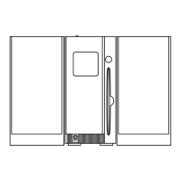
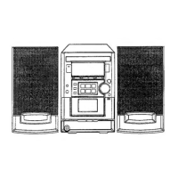
Visual representation of internal components and their positions.
Detailed list of mechanical parts with reference numbers.
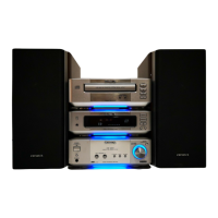
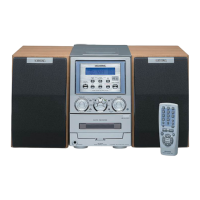
The AIWA XR-MS3 is a compact disc stereo system, available in EZ and K models, with a black finish for the EZBM variant. This service manual serves as a supplement, replacing the "Simple Manual" XR-MS3 (EZ,K) (S/M Code No. 09-004-422-6T2). It specifically details the XR-MS3 (EZBM) black color model and provides information on the differences between XR-MS3 (EZBM,KSM) and XR-MS3 (EZ). For other information, users are directed to the Service Manual of XR-MS3 (U,EZ) (S/M Code No. 09-002-422-6R1). Note that the "CD ELECTRICAL SECTION" is not included in this manual and will be issued in a future supplement.
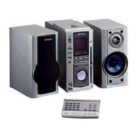
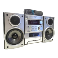
The XR-MS3 is a versatile stereo system integrating a compact disc player, a cassette deck, and a tuner, designed for comprehensive audio playback. It features a basic tape mechanism (2ZM-1 R10NM) and a basic CD mechanism (TN-CCD1001-902M). The system is equipped with speakers (SX-M7 for EZ, SX-MS7 for K) and a remote controller (RC-AAT03(B) for EZ, RC-AAT03 for K) for convenient operation.
The XR-MS3 offers a comprehensive audio experience with its integrated CD player, cassette deck, and tuner. The inclusion of a remote controller enhances user convenience, allowing control from a distance. The system's compact dimensions make it suitable for various living spaces. The magnetic shielded speakers ensure minimal interference with other electronic devices. The presence of a digital optical output allows for high-quality audio connection to compatible external devices. The system also features a headphone jack for private listening.
The service manual provides detailed electrical main parts lists, wiring diagrams, and schematic diagrams for various sections of the device, including the main C.B (amplifier and micon sections), front C.B, HP-Jack C.B, PT C.B, tuner C.B, tape C.B, deck C.B, and relay C.B. These resources are crucial for troubleshooting, repair, and replacement of components. The mechanical exploded view and mechanical parts list facilitate the disassembly and reassembly of the unit for maintenance purposes. The manual also includes a color name table for easy identification of components. The specifications highlight the use of Dolby noise reduction and BBE Sound technologies, which may require specific maintenance procedures as outlined by their respective licensing corporations. Design and specifications are subject to change without notice, indicating that users should refer to the latest available documentation for the most accurate information.
| Brand | Aiwa |
|---|---|
| Model | XR-MS3 |
| Category | Stereo System |
| Language | English |