EasyManua.ls Logo

Aiwa XR-MS5 K - User Manual

Aiwa XR-MS5 K
59 pages
Print Icon
To Next Page IconTo Next Page
Loading...
SERVICE MANUAL
DATA
CXLMS5XRMS5
RCBAT01
SYSTEM
CD
CASSEIVER
REMOTE
CONTROLLER
COMPACT DISC
STEREO SYSTEM
BASIC CD MECHANISM : AZG-X A1NM
XR-MS5
XR-MS6
K
EZ
S/M Code No. 09-015-441-8R2
SPEAKER
SXLMS5
This Service Manual is the Revision Publishing and replaces Simple Manual
(S/M Code No. 09-012-441-8T2).
REVISION
CXLMS6XRMS6
SIMPLE-2
Apartofcontentsisadequate.
Re-issuing is under request.
All manuals and user guides at all-guides.com
all-guides.com
Question and Answer IconNeed help?

Do you have a question about the Aiwa XR-MS5 K and is the answer not in the manual?

Overview

This document provides a service manual for the Aiwa XR-MS5 and XR-MS6 SIMPLE-2 compact disc stereo systems. It includes detailed information for servicing, technical specifications, and operational features.

Function Description:

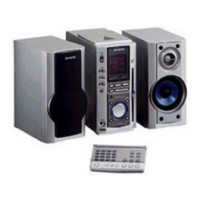
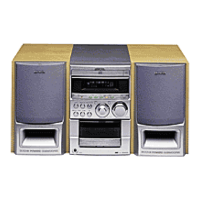
The Aiwa XR-MS5 and XR-MS6 are compact disc stereo systems, categorized as CLASS 1 LASER products. They integrate a tuner, amplifier, and CD player into a single unit. The system is designed for audio playback from compact discs, radio reception (FM, MW, LW), and external audio sources via auxiliary inputs. It also supports headphone output and a super woofer output.

Important Technical Specifications:

Main Unit (CX-LMS5/CX-LMS6):

  • Power Requirements: 230 V AC, 50 Hz
  • Power Consumption: 45 W
  • Power Consumption in Standby Mode:
    • With ECO mode on: 1.3 W
    • With ECO mode off: 12 W
  • Dimensions (W x H x D): 100.0 x 205.0 x 292.5 mm
  • Weight: 3.5 kg

Tuner:

  • FM Tuning Range: 87.5 MHz to 108 MHz
  • FM Usable Sensitivity (IHF): 16.8 dBf
  • FM Antenna Terminal: 75 ohms (unbalanced)
  • MW Tuning Range: 531 kHz to 1602 kHz (9 kHz step) / 530 kHz to 1710 kHz (10 kHz step)
  • MW Usable Sensitivity: 350 µV/m
  • LW Tuning Range: 144 kHz to 290 kHz
  • LW Usable Sensitivity: 1400 µV/m
  • MW/LW Antenna: Loop antenna

Amplifier:

  • Power Output:
    • Rated: 12 W + 12 W (6 ohms, T.H.D. 1%, 1 kHz/DIN 45500)
    • Reference: 15 W + 15 W (6 ohms, T.H.D. 10%, 1 kHz/DIN 45324)
    • DIN MUSIC POWER: 22 W + 22 W
  • Input: VIDEO/AUX: 600 mV
  • Outputs:
    • SPEAKERS: 6 ohms or more
    • PHONES: 16 ohms or more
    • SUPER WOOFER: 0.85 V
    • DIGITAL OUT (OPTICAL) jack
    • LINE OUT jack

CD Player:

  • Laser: Semiconductor laser (λ = 780 nm)
  • D/A Converter: 1 bit dual
  • Signal-to-Noise Ratio: 85 dB (1 kHz, 0 dB)
  • Harmonic Distortion: 0.08% (1 kHz, 0 dB)
  • Wow and Flutter: Unmeasurable

Speaker System (SX-LMS5):

  • Speaker System: 2 way, bass reflex (magnetic shielded)
  • Speaker Units: Woofer: 85 mm cone, Tweeter: 22 mm dome
  • Impedance: 6 ohms
  • Dimensions (W x H x D): 100 x 210 x 185 mm
  • Weight: 1.5 kg

Usage Features:

The system features a front panel with various controls, including a jog dial for volume/multi-jog functions, tuning up/down buttons, preset buttons, and function selection. It includes a display (FL101) for showing operational status and settings. The remote sensor (IC101 GP1U271X) allows for remote control operation. The CD player supports standard playback functions, including search and play modes, and features a loading mechanism for disc insertion. The tuner allows for FM, MW, and LW band selection. The amplifier provides audio output to speakers, headphones, and a super woofer.

Maintenance Features:

Protection of Eyes from Laser Beam During Servicing:

The manual emphasizes strict adherence to safety precautions when servicing the device due to the presence of a laser. Technicians are warned not to approach the laser exit too closely and to observe from a distance of more than 30cm from the surface of the objective lens on the optical pick-up block to avoid exposure to invisible laser radiation. Using controls, adjustments, or procedures other than those specified in the manual may result in hazardous radiation exposure.

Precaution to Replace Optical Block (KSM – 900AMA):

When replacing the optical block, technicians must ground their body and workbench to prevent electrostatic discharge from ruining the laser diode. Care must be taken to avoid touching the diode with clothing. After connection, specific solder points must be removed.

Disassembly Instructions:

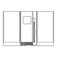
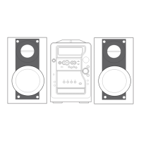
The manual provides detailed, step-by-step instructions for disassembling the AZG-X mechanism and placing it in a service position. This includes removing side panels, the top panel, and the front assembly. Specific steps are outlined for disconnecting flexible flat cables (FFC) and connectors. Instructions are also provided for removing the PWB, CD, and PLATE CD RE, emphasizing careful handling of slits and bosses during reassembly. Further steps detail the removal and reassembly of the CD MECHA ASSY, PLT, SLIDER, LVR, ROLLER ASSY, and MOTOR ASSY, with illustrations to guide the process and highlight critical alignment points (e.g., rubber dampers, damper hooks, gear positions, screw bosses, and motor label direction).

CD Test Mode:

A dedicated CD Test Mode is available for diagnostics.

  • Starting the Test Mode: Press and hold the ENTER key while connecting the AC power plug. All indicators will light up.
  • Exiting the Test Mode: Press the POWER button, any button other than CD, or disconnect the AC power plug.
  • Function Descriptions: The test mode offers various functions:
    • Start Mode: All indicators light, used for FL check and microprocessor check.
    • Search Mode: (Activated by STOP button) Performs TOC reading, LD emits laser light, continuous focus search, and allows checking APC circuit, laser current, and focus search waveform.
    • Play Mode: (Activated by Play button) Normal playback, repeats search mode if TOC reading fails, used for checking focus servo, tracking servo, sled servo, spindle servo, FOK, and RF waveform.
    • Traverse Mode: (Activated by PAUSE button) ON/OFF repeats when tracking servo is pressed, used for checking tracking servo and traverse waveform.
    • Sled Mode: (Activated by FF/REW buttons) Moves optical pickup to outer/inner circumference, used for checking sled circuit and mechanism.
  • Tray Test Mode: (Activated by TUNER/BAND key in CD test mode) Allows checking the loading mechanism, including motor rotation (F for loading, R for unloading) and detection switches (DISC IN, 12cm/8cm disc detection, loading end switch).

Adjustments (Tuner/Micon):

The manual includes detailed adjustment procedures for the tuner and micro-controller sections, covering:

  • Clock Frequency Check
  • MW VT Check and Tracking Adjustment
  • LW VT Check and Tracking Adjustment
  • AM IF Adjustment
  • FM VT Adjustment and Tracking Adjustment
  • DC Balance / Mono Distortion Adjustment
  • Output Level Check (MW and FM)
  • FM Separation Check
  • µ-CON OSC Adjustment

These procedures involve setting specific frequencies, adjusting components (e.g., L951, L942, L801, L901, L902, L904, L905, L907, L101), and verifying output levels, voltages, distortion, and frequency readings at designated test points (TP1, TP2, TP3, TP4, TP8, TP9).

Aiwa XR-MS5 K Specifications

General IconGeneral
BrandAiwa
ModelXR-MS5 K
CategoryStereo System
LanguageEnglish

Related product manuals