EasyManua.ls Logo

Aiwa Z-L800 User Manual

Aiwa Z-L800
46 pages
To Next Page IconTo Next Page
Page #1 background imageLoading...
Page #1 background image
SERVICE MANUAL
DATA
COMPACT DISC STEREO
CASSETTE RECEIVER
BASIC TAPE MECHANISM : 2ZM-3MK2 PR5NM
BASIC CD MECHANISM : 6ZG-1 ZRDM
Z-L700
Z-L800
U
LH
S/M Code No. 09-004-422-7R1
REVISION
• If requiring information about the CD mechanism, see Service Manual of 6ZG-1,
(S/M Code No. 09-001-338-7N2).
• This Service Manual is the “Revision Publishing” and replaces “Simple Manual”
Z-L700 (U) / Z-L800 (LH), (S/M Code No. 09-002-422-7T1).
Z-L700
SPEAKER
SYSTEM
CD
CASSEIVER
SX-WZL700CX-ZL700
RC-ZAS12
STEREO
TURNTABLE
Z-L800
CX-ZL800 SX-WZL800
REMOTE
CONTROLLER
PX-E860
-
• If requiring information about the Stereo Turntable, see Service Manual of
PX-E860 (U), (S/M Code No. 09-993-322-0R1).
All manuals and user guides at all-guides.com
all-guides.com
Question and Answer IconNeed help?

Do you have a question about the Aiwa Z-L800 and is the answer not in the manual?

Aiwa Z-L800 Specifications

General IconGeneral
TypeMini Hi-Fi System
CD PlayerYes
Frequency Response20Hz - 20kHz
Speaker Impedance6 Ohms
Remote ControlYes
Tuner BandsFM/AM
Speakers2-way speakers

Summary

Specifications

FM Tuner Section

Details FM tuner specifications, including tuning range and sensitivity.

AM Tuner Section

Details AM tuner specifications, including tuning range and sensitivity.

Amplifier Section

Specifications for the amplifier's power output and distortion.

Compact Disc Player Section

Specifications for the CD player's laser and D-A converter.

Cassette Deck Section

Specifications for the cassette deck's frequency response and S/N ratio.

Speaker System SX-WZL700 (U)

Specifications for the SX-WZL700 speaker system.

Speaker System SX-WZL800 (LH)

Specifications for the SX-WZL800 speaker system.

General

General specifications including power requirements and dimensions.

Protection of Eyes from Laser Beam During Servicing

Laser Safety Precautions

Provides crucial warnings and cautions for safe laser beam servicing.

Notes on Before Starting Repair

Forced Discharge of Electrolytic Capacitor

Procedure to safely discharge power supply capacitors before repair.

Microcomputer Troubleshooting Checks

Checks for HOLD terminal, reset procedure, and soldering state.

Transistor Illustration

Wiring - 1 (MAIN/VM)

Schematic Diagram - 2 (Main 2/3 <Deck> / Head - 1/ Head - 2)

Schematic Diagram - 3 (Main 3/3 <Tuner>)

Wiring - 2 (MICON)

Schematic Diagram - 4 (MICON/Deck)

Wiring - 3 (CNTL)

Schematic Diagram - 5 (CNTL/MIC/Key CD/ DK1 LED / DK2 LED)

Schematic Diagram - 6 (U: AMP IF)

Schematic Diagram - 7 (LH: AMP IF)

Wiring - 6 (U: PT)

Schematic Diagram - 8 (U: PT)

Wiring - 7 (LH: PT)

Schematic Diagram - 9 (LH: PT)

Wiring - 8 (Key CD / DK1 LED / DK2 LED / MIC)

Wiring - 9 (Deck / Head-1 / Head-2)

IC Block Diagram

Adjustment Procedures

Tuner Section Adjustments

Covers adjustments for FM and AM tuning frequency and VT.

Deck Section Adjustments

Covers tape speed, azimuth, and frequency response adjustments.

Front Section Adjustments

Covers MICON OSC adjustment.

Mechanical Exploded View 1/1

Mechanical Parts List 1/1

Tape Mechanism Exploded View 1/1

Tape Mechanism Parts List 1/1

Speaker Disassembly Instructions

Disassembly Types

Details on different methods for speaker unit and panel removal.

Panel FR Removal and Attachment

Procedures for removing and attaching the front speaker panel.
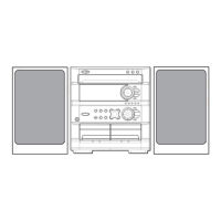
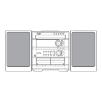
Speaker Parts List

Accessories / Package List

Related product manuals