Do you have a question about the Aiwa Z-L900 and is the answer not in the manual?
Details for the FM radio tuning range and sensitivity.
Details for the AM radio tuning range and sensitivity.
Specifications for power output, distortion, and input/output levels.
Specifications for tape format, frequency response, and heads.
Specifications for laser, D-A converter, and distortion.
Details on speaker cabinet type, drivers, impedance, and SPL.
Power requirements, consumption, and main unit dimensions/weight.
Precautions for handling optical blocks to prevent damage to diodes.
Steps to safely discharge power supply capacitors before repair.
Procedures to check microcomputer function before replacement.
Method for performing a forced reset on the microcomputer.
Verifying soldering quality of the microcomputer before replacement.
Mapping of FL display grid points to segment control signals.
Procedures for adjusting tuner frequency, VT, tracking, and IF stages.
Procedures for adjusting tape speed, azimuth, and frequency response.
Procedure for adjusting the microcomputer oscillator frequency.
Instructions for removing speaker panels and units using basic tools.
Instructions for removing speaker grills, panels, and units with rubber caps.
Instructions for removing speaker units by rotating them counter-clockwise.
| Remote Control | Yes |
|---|---|
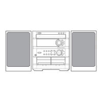
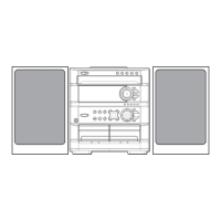
| Type | Mini Hi-Fi System |
| CD Player | Yes |
| Cassette Deck | Double Cassette Deck |
| Tuner | Yes, AM/FM |