1
7
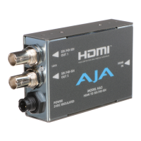
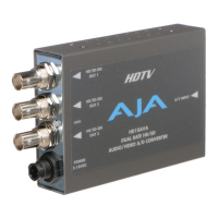
AJA ADA4 4-Ch Bi-directional Audio A/D and D/A Converter User Manual — User Controls
Switches 3 and 4 (LEVEL)—Controls audio levels (see matrix below)
Note:
Professional audio equipment has much higher levels than consumer equipment: a 0
VU reading corresponds to +4 dBu. Connecting a professional +4 dBu device to a consumer
audio input -10dBV (
-7.8 dBu)
may cause overloading, whereas the output of a consumer
device probably does not have sufficient power to drive a professional audio input. With
consumer and semi-professional audio equipment, a VU reading of 0 dB is typically
referenced to -10 dBV. 0 dBu = 0.775 VRMS.
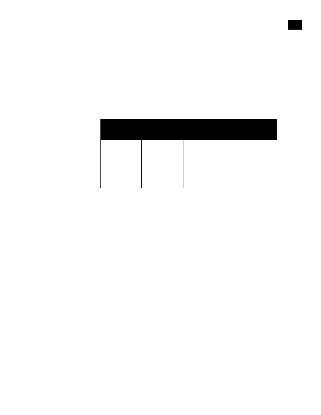
Output Level Selection Matrix For Switches 3 and 4
The following table shows the combinations of DIP switch settings required to configure the
audio output levels shown.
48 KHz/96KHz
Output Mode
(Jumper 1)
Jumper#1 selects how the AES outputs and the AES11 reference output run. If Jumper 1 is
installed, they run in 48 KHz mode. If Jumper 1 is removed, they run in 96 KHz mode.
Synchronizer
Mode
(Jumper #2
Removed)
Synchronizer
mode is an alternative operating mode where no audio A/D or D/A conversion
takes place. Instead, it allows for an AES input to be sample rate converted and reclocked to
reveal an AES output that is low jitter, and—when a reference signal is applied—locked to
reference. In this mode the DIP switches are ignored and all configuration options are set via
a 3-position jumper located inside the ADA4 case. To access this jumper, remove the four
phillips screws securing back side of the ADA4 case (the side having the DIP switch access
hole in it). Once the case cover is removed, you can easily identify the jumper by its
appearance. Jumper positions 1 through 3 are clearly marked on the circuit board next to the
jumper. Refer to the following diagram for jumper settings and their meaning.
DIP Switch #4
(LEVEL 2)
DIP Switch #3
(LEVEL 1) Output Level
0 0 Pro USA: 0dBFS
→
+24dBu
0 1 Pro Europe: 0dBFS
→
+18dBu
1 0 Pro Germany: 0dBFS
→
+15dBu
1 1 Consumer: 0dBFS
→
+12dBu