8
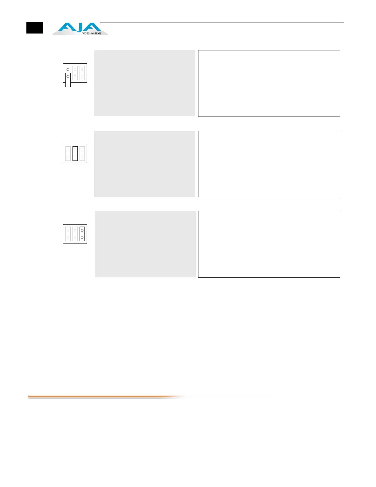
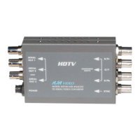
ADA4, Internal Jumper Settings
Jumper 3
Jumper#3 is currently unused.
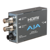
Lock LED
An LED is located next to the BNC connectors which shows the type of signal locked (if
any). Here are the meanings of the LED colors:
•
Red = HD lock
•
Green = SD lock
•
Amber = AES-11 lock or Word Clock lock
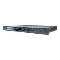
Installation
Typically, ADA4 installation consists of the following:
1.
disconnect +5VDC from the converter
2.
configure the DIP switch for the desired equipment configuration
3.
connect video equipment to the converter BNCs
4.
apply +5VDC power to the converter (AJA power supply model DWP)
Example:
Normal mode selected.
Meaning:
Jumper 2 installed—Normal Mode: Switches 1 and 2
independantly define A/D or D/A mode for their
respective pair of channels. Switches 3 and 4 are
used together to define the audio level.
Jumper 2 removed—Synchronizer Mode: Switches 1-4 have
no effect. The ADA4 is in D/D mode, with the output
re-timed to the reference signal, when applied.
Without a reference signal applied, the ADA4 re-
clocks the output based on its stable free-running
local oscillator.
Jumper 1:
1 23
Example:
96kHz output mode selected
(jumper effectively removed).
Jumper 2:
1 2 3
Meaning:
Jumper 1 installed—48kHz: Any AES outp uts and the AES-11
reference output are running in 48kHz mode.
Jumper 1 removed—96kHz: Any AES ou tputs and the AES-11
reference output are running in 96kHz mode.
Note:
Jumper 3 is not used, but is provided as
a spare.
Jumper 3:
123
Meaning:
n/a: Jumper 3 is not used.