C10DA Mini-Converter v1.0r1 www.aja.com
7
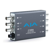
Gain Control The positions of DIP Switches 3, 2, and 1 determine the gain setting, from -3dB to +3dB in
1dB increments, as indicated in the illustration below.
DIP Switch
Configuration
Example 1
Input is Terminated In example 1, DIP Switch 4 is positioned to the left, meaning that the input is terminated.
Gain Control Set to
+1dB
In example 1, DIP Switches 3, 2, and 1 are configured for a gain control setting of +1dB.
DIP Switch
Configuration
Example 2
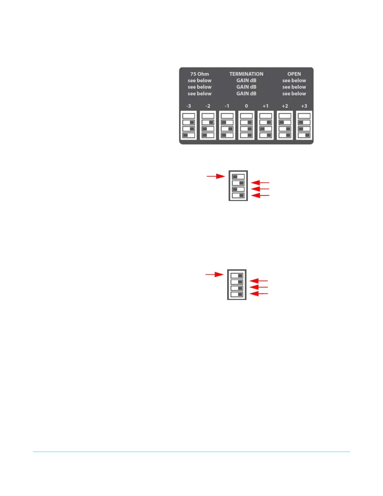
Input is Open In example 2, DIP Switch 4 is positioned to the right, meaning that the input is open.
Gain Control Set to 0 In example 2, DIP Switches 3, 2, and 1 are configured for a gain control setting of 0.
Dip switch
numbering:
4
3
1
2
Dip switch 4 positioned to
the left (Input is terminated)
Dip switches 3, 2, and
1 are set for a gain
setting of +1dB
Dip switch 4 positioned to
the right (Input is open)
Dip switches 3, 2, and
1 are set for a gain
setting of 0