QR
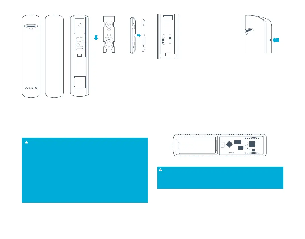
PICTURE 1. The sensor’s
and the big magnet’s
fastening clip
Move down
and
lift up
PICTURE 2.
Small magnet
assembling
5.2 Install the fastening clip SmartBracket on the door frame and door or window frame
and window with a help of the expansion bolts and self-tapping screws included in the set.
5.3 Put the sensor on the SmartBracket. Once the sensor is fi xed on the SmartBracket, its
light must blink. It means that the tamper on the sensor is shut. In case the sensor does not
blink, the tamper status must be checked at the receiver confi guration software!
ATTENTION!
Small magnet fi ts better for the installing when the door shut and the door jamb are
perpendicular. Big magnet fi ts better for the installing with the door shut and the
door jamb to be in a single plane. Be careful while installing the assembling clip.
Overexertion while installing can cause deformation and, as a result, impossibility to
install the sensor or to its unreliable fastening. The main body of the sensor is to be
installed on the fi xed part of door frame or window frame, and the magnet is to be
installed on the moving part of the door or window. The magnet is to be located in
parallel with the sensor’s main body and opposite to the special sign (triangle) on it
(PICTURE 4). Fix the SmartBracket with the set’s assembling units only! Other fi xing
system use, for example, self-tapping screws of big diameter, can damage fastening
clip. Together with self-tapping screws, there is a double stick tape in the set. It can be
used for temporary sensor fi xing only. It is recommended not to use the tape for the
permanent fi xing, as the tape is drying up over a time and the sensor may fall down
which can cause alarm actuation.
5.4 The opening detection sensor is installed!
5.5 In order to connect an additional wire sensor, plug in its wire to the socket “4” (PICTURE
3) on the sensor, and pass the wire through the sensor’s opening having removed the
cover “5” (PICTURE 3) from the sensor.
1 – Front cover trigger
2 – Cut-off switch
3 – Tamper button
4 – Socket for wire sensors
5 – Cover on the sensor for the wire
sensors’ wires
1
2
ON
OFF
5 5
4
3
PICTURE 3.
The sensor’s back cover
5.6 The longer the wire of the removable sensor is, the bigger are the risks of its accidental
damage and the lower is the coverage quality. The distance suggested between the
removable sensor and the wireless sensor Ajax is no more than 1 m.
PICTURE 4.
Triangle detecting the sealed contact
6. MAINTENANCE
6.1 Maintenance is done once every 6 months. The sensor’s board must be cleared of dust,
spider web, and other impurities.
6.2 Never rub the sensor with substances containing alcohol, acetone, petrol and other
active solvents.
6.3 Replace the batteries up to date. If the battery level is low, the sensor sends an
appropriate signal to the alarm system receiver unit. When the battery has run down, with
detection, including the tamper triggering, the sensor together with a usual indication turns
on its light and turns it off placidly. In order to replace the battery, lift up the trigger “1”
(PICTURE 3) and remove the sensor’s front cover. Replace the «battery» (PICTURE 5) with
a new one, type CR123A.
PICTURE 5. The sensor with the back cover removed.
battery –+
ATTENTION!
The sensor’s autonomous work duration depends on the sensor’s triggering frequency
and the battery quality. With door opening 10 times per day and the 60 seconds of
sampling time, the battery life is 7 years. With door opening 60 times per hour and 12
seconds of polling period, the battery life of the new battery is approximately 2 years.
7. WARRANTY
7.1 The sensor’s warranty period is 24 months. The warranty does not cover the battery!
8. VIDEO GUIDE
8.1 A detailed video guide for Ajax DoorProtect sensor assembling and assessing is available
online on our website.
AJAX Systems Inc., www.ajax.systems, support@ajax.systems
 Loading...