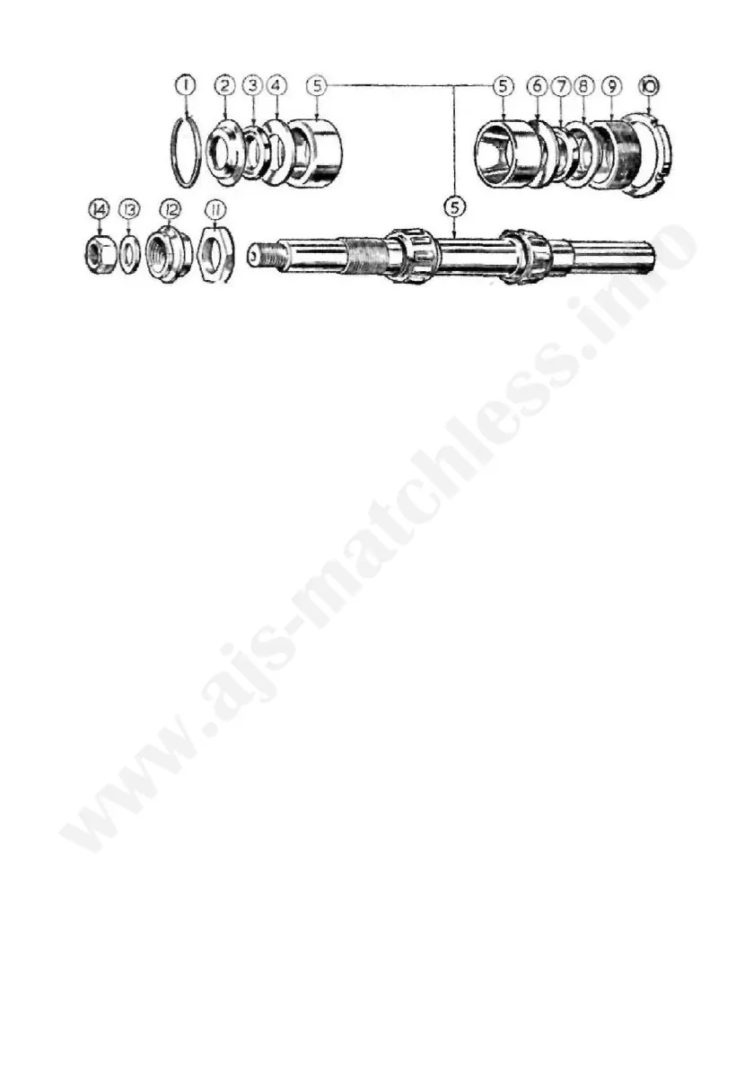
FIG 26 Front wheel bearings
1 Circlip
2 Oil seal cup
3 Oil seal
4 Washer retaining seal
5 Wheel spindle complete
6 Washer retaining seal
7 Oil seal
8 Oil seal cup
9 Adjusting ring
10 Adjusting ring locknut
11 Nut locating brake coverplate
12 Nut securing brake coverplate
13 Spindle end washer
14 Spindle end nut
Avoid using heavy hammer blows when taking the spindle out, as this
action can cause indentations in the bearing sleeve.
Adjusting the front wheel bearing. Release the locking ring (10), screw
in the adjusting ring (9) until the bearing is devoid of end movement,
unscrew the adjusting ring half a turn only, give the opposite end of the
spindle a light blow to move the bearing ring away from the bearing.
Position the cover disc and firmly retighten the lock ring.
There should be approximately .002" side rock at the wheel rim if the
adjustment is correct. The friction of the oil seals can create a false im-
pression that the bearing is tight.
Dismantling rear wheel bearing (Fig. 28). Before removing the rear wheel,
release the speedo drive fixing nut (16), disconnect speedo cable and take
out the wheel.
Remove the nut (16) and speedo gear box, release the lock ring (13).
Remove adjuster sleeve (14) and speedo gear box sleeve (2), and cover
disc.
Remove the washer (3), oil seal (4) and oil seal cup (5); also distance
piece (6).
Turn to the brake side of the hub, when with the use of a short steel
rod or tubing, with an external diameter of J" drift out the hub internals,
leaving the bearing ring (7) in situ.
To remove the bearing ring. Press inwards the steel cup washers (5) to
permit extraction of the circlip (11), take out the cup washer, oil seal and
spacer (6). Drift out the bearing ring with a length of steel tubing.
NOTE—When refitting the circlip press back the bearing ring. See 'Wheel
bearing adjustment'.
88