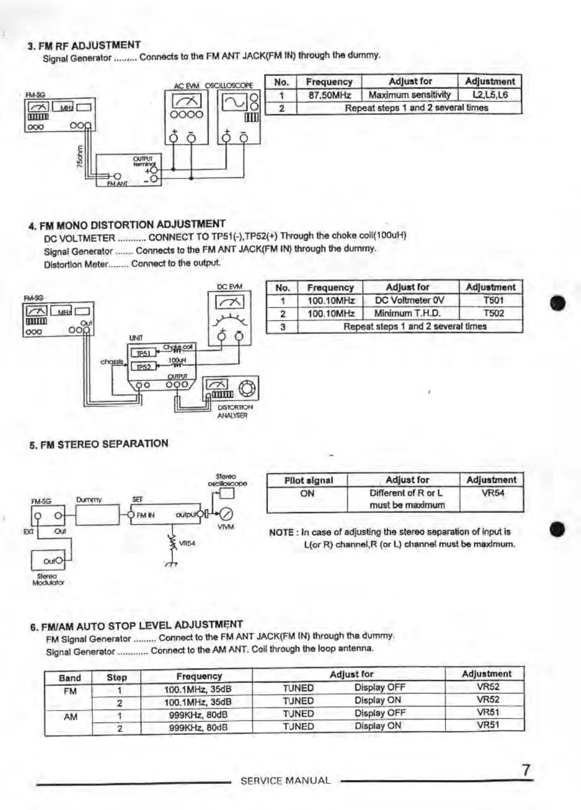
3. FM RF ADJUSTMENT
Signal Generator ..... , ... Connects to the
FM
ANT
JACK(FM IN) through the dummy.
l>C
EVM
OSCILLOSCOflc
No
.
Frequency
Adjust
for
Adjustment
·
FM-SG
1
87.50MHz
Maximum
sensitivity
L2,l5,L6
1/'AI
!'vl8
,,..,'-IGti.Jo
2
Repeat steos 1 and 2 several
limes
0000
IIIIl
IIJDlll
000
oc
) .
-)
~
i
~
OU1M
F'!:{J _
-
4.
FM MONO DISTORTION ADJUSTMENT
DC
VOLTMETER ........... CONNECT
TO
TP51(-),TP52(•) Through the
choke
coil(100uH)
Signal Generator ....... Connects
to the
FM
ANT
JACK(FM IN) through
the
dummy.
Distortion Meter ........
Connect to the output.
OCEVM
No.
Frequency
Adjust
for
Adjustment
FM-SG
I l'""7\ I
ln<-111.dw!D
1 100.10MHz
DC
Voltmeter OV
T501
2
100
.1
0MHz
Minimum T.H.D. T502
amm
00().Jt
~
000
-o
,"')
3
Repeat steps 1 and 2 several times
UNIT
001
I =<>
ct~
-
10Wi
I
-
--
'1"10
0
01
1~01
"'
"'
OCSIC<lllON
ANAI.VSER
6. FM STEREO SEPARATION
PIiot signal .
Adjustfor
Adjustment
ON
Different
of
R or L VR54
must
be
maximum
NOTE :
In
case
of
adjusting the stereo separation
of
input
is
L(or R) channel,R
(or
L) channel
must
be
maximum.
6. FM/AM
AUTO
STOP
LEVEL
ADJUSTMENT
FM Signal Ger>erator ......... Connect to the
FM
ANT
JACK(FM IN) through the dummy.
Signal Generator ............ Connect to the
AM
ANT. Coil through the
loop
antenna.
Band
Step
Frequency
Adjustror
Adjustment
FM
1
100.1MHz, 35dB
TUNED
Display
OFF
VR52
2
100.1 MHz, 35dB
TUNED
Display
ON
VR52
AM
1
999KHz, 80dB
TUNED
Display
OFF
VR51
2
999KHz, 80dB
T\.JNED
DlsplavON
VR51
SERVICE
MANUAL
•
•
7