Do you have a question about the Akai AA-1125 and is the answer not in the manual?
Lists technical specifications for the amplifier section, including power output, bandwidth, and sensitivity.
Lists technical specifications for the FM and AM tuner sections, including sensitivity and selectivity.
Lists technical data for transistors, diodes, power requirements, dimensions, and weight.
Visual guide for disassembling the unit, showing panel, cabinet, and internal parts.
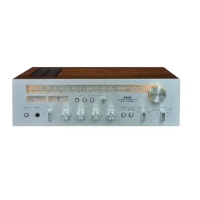
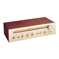
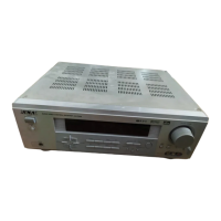
Identifies front and rear controls for the AA-1115 model.
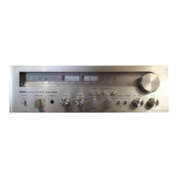
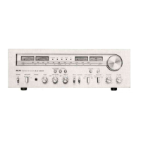
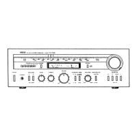
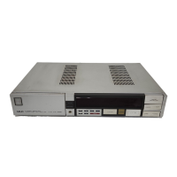
Identifies front and rear controls for the AA-1125 model.
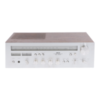
Illustrates the location of major components for the AA-1115 model.
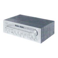
Illustrates the location of major components for the AA-1125 model.
Details the block diagram and operating principles of the detection system.
Explains the feedback mechanism of the PLL circuit for signal lock.
Illustrates signal levels through different stages for both models.
Detailed steps for adjusting the tuner sections.
Procedure for adjusting idling current for left and right channels.
Instructions and diagrams for threading the tuning cord.
Lists P.C board identification numbers for AA-1115 and AA-1125.
Exploded views of AA-1115 P.C boards for different regions.
Exploded views of AA-1125 P.C boards for different regions.
Instructions on how to read and order parts from the list.
Lists spare parts recommended for stocking to facilitate repairs.
Lists components for various assembly blocks and P.C. boards.
Lists interchangeable semiconductor parts for service replacements.
Detailed schematic diagram for the AA-1115 model.
Detailed schematic diagram for the AA-1125 model.
Schematic for the front end section common to both models.
| Tuning range | FM, MW |
|---|---|
| Frequency Response | 20Hz to 20kHz |
| Input Sensitivity | 2.5mV (MM), 150mV (line) |
| Speaker Impedance | 4Ω to 16Ω |
| Power Output | 25 watts per channel into 8Ω (stereo) |
| Total Harmonic Distortion | 0.5% |
| Signal to noise ratio | 70dB (MM) |
| Output | Headphones |