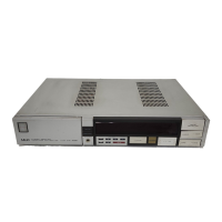
Do you have a question about the Akai AA-R22/L and is the answer not in the manual?
Overview of the AA-R series system architecture and control.
Details the operation of the amplifier section controlled by the AA-100 IC.
Explains the tuner section control operations managed by the AT-600 IC.
Describes the AKAI Zero Drive circuit for distortion correction.
Explains the Dual-Pole DC Servo circuit for amplifier characteristic improvement.
Lists detailed technical specifications for the AA-R22/L stereo receiver.
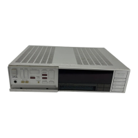
Provides step-by-step instructions for disassembling the unit.
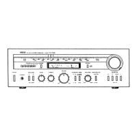
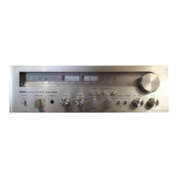
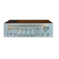
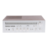
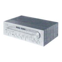
Identifies and describes the front panel controls of the receiver.
Shows the location of key components on the unit's PCBs.
Explains voltage conversion and selector functions like FM de-emphasis.
Details procedures for clock frequency and tuner adjustments.
Lists titles and identification numbers for all PC boards.
Lists detailed technical specifications for the AA-R32/L stereo receiver.
Provides step-by-step instructions for disassembling the unit.
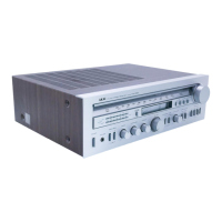
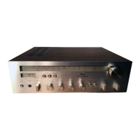
Identifies and describes the front panel controls of the receiver.
Shows the location of major components on the unit's PCBs.
Explains voltage conversion and selector functions like FM de-emphasis.
Details procedures for clock frequency and tuner adjustments.
Lists titles and identification numbers for all PC boards.
Lists recommended spare parts for the AA-R22/L stereo receiver.
Lists recommended spare parts for the AA-R32/L stereo receiver.
Lists recommended spare parts for the AA-R42 stereo receiver.
Provides schematic diagrams for various integrated circuits used in the unit.
Shows the connection diagram for the AA-R22/L receiver.
Presents the schematic diagram for the AA-R22 tuner section.
Presents the schematic diagram for the AA-R22L tuner section.
Shows the connection diagram for the AA-R32/L receiver.
Presents the schematic diagram for the AA-R32/L amplifier section.
Presents the schematic diagram for the AA-R32 tuner section.
Shows the connection diagram for the AA-R42 receiver.
Presents the schematic diagram for the AA-R42 amplifier section.
Presents the schematic diagram for the AA-R42 tuner section.
| Brand | Akai |
|---|---|
| Model | AA-R22/L |
| Category | Stereo Receiver |
| Language | English |