6. OPERATION
OF
ELECTRONIC VOLUME CONTROL
AND
TONE CONTROL
6-L
OPERATION
OF
ELECTRONIC
VOLUME
CONTROL
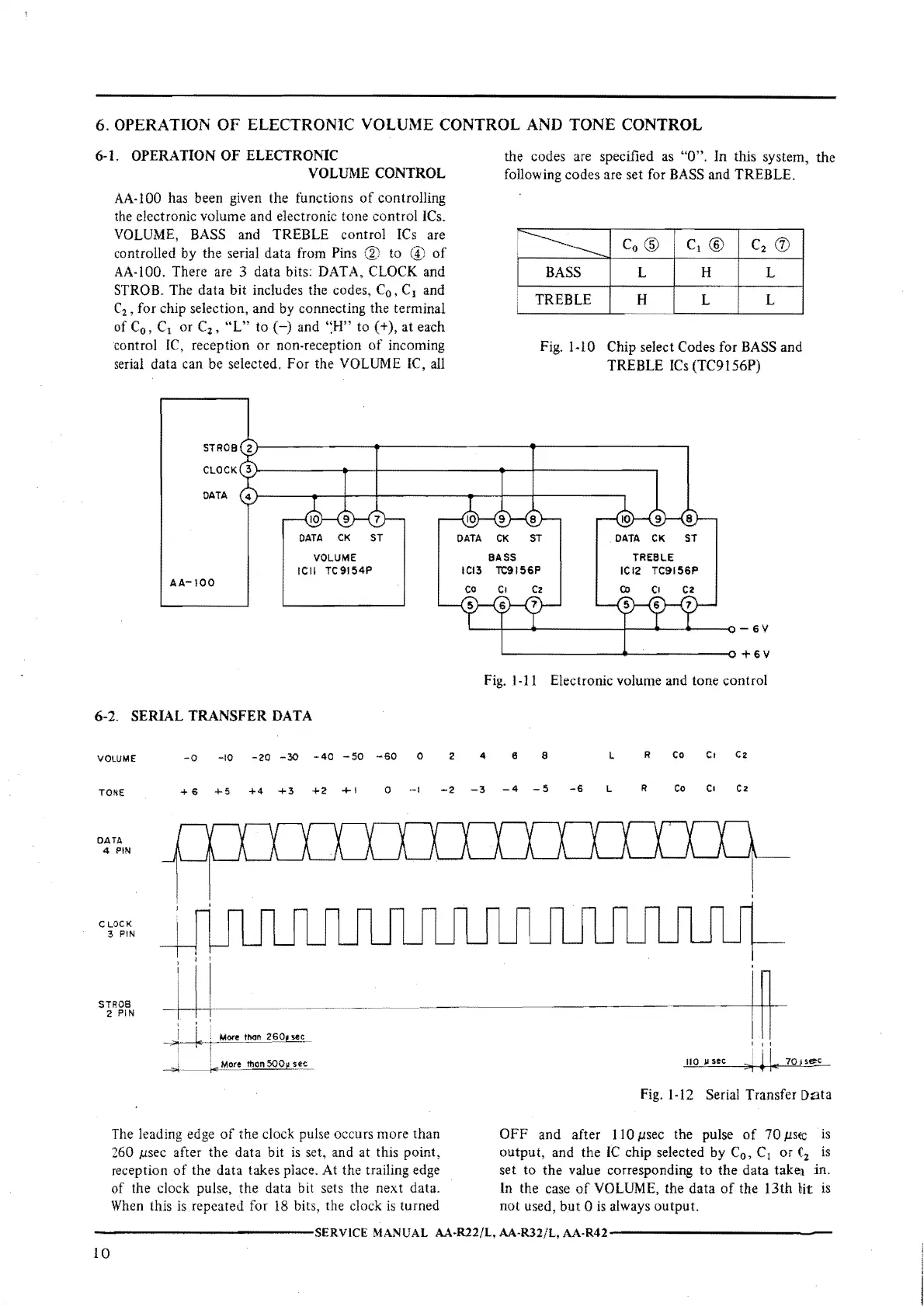
AA-100 has been given
the
functions
of
controlling
the electronic volume and electronic tone
control
ICs.
VOLUME, BASS and TREBLE control
ICs
are
controlled
by
the
serial
data
from Pins ® to
of
AA-100. There are 3 data bits: DATA, CLOCK and
STROB. The
data
bit
includes the codes, C
0
,
C
1
and
C
2
,
for chip selection, and by connecting the terminal
of C
0
,
C
1
or C
2
,
''L"
to
(-)
and ''.H" to
(+),at
each
control IC, reception
or
non-reception
of
incoming
serial data can be selected.
For
the VOLUME IC, all
DATA
CK
ST
VOLUME
ICII
TC9154P
AA-
100
6-2.
SERIAL
TRANSFER
DATA
VOLUME
-o -10
-20
-30
-40
-50
-60
0
2
the codes are specified as "O".
In
this system,
the
following codes are set for BASS and TREBLE.
.
------
Co@
C1@
C2
(J)
I
i
BASS L H
L
TREBLE
H L L
Fig.
1-10
Chip select Codes for BASS and
TREBLE
ICs
(TC9156P)
'-------------~+6V
Fig.
1-11
Electronic volume and
tone
control
4 e a L
R Co Ct C2
TONE
+ 6
+5
+4
+3
+2
+ I
0
··I
-2
-3
-4
5
-6
L
R
Co
c,
Cz
DATA
4 PIN
CLOCK
3 PIN
STR0S
2 PIN
More
tl'l<ln
2so,
sec_
More thon
500p
see
The leading edge
of
the
clock pulse occurs more
than
260 µsec after the data bit
is
set, and at this point,
reception
of
the data takes place. At the trailing edge
of
the clock pulse, the data bit sets the
next
data.
When
this
is
repeated for
18
bits, the clock
is
turned
I I I
110
µ sec
c>j
!
1.,
7Q)S6'..£__
Fig.
1-12
Serial Transfer
Data
OFF
and after 110 µsec the pulse
of
70
µste
is
output,
and the
IC
chip selected by C
0
,
C
1
or
(
2
is
set
to
the
value corresponding
to
the data takei
in.
In the case
of
VOLUME, the
data
of
the 13th bit
is
not
used,
but
O
is
always
output.
-------------SERVICE
MANUAL
AA·R22/L,
AA-R32/L,
AA-R42-------------
 Loading...