IV.
AKAi
ZERO
DRIVE
CIRCUIT
(AA-R42/R32)
1.
IN
THE BEGINNING:
Many techniques concerned with negative feedback
(NF) such
as
NON
NFB, low feedback amplifier,
super
FF, linear feedback and pure NF have been
much talked
about
in
the
world
of
audio. All these
techniques were developed
to
compensate for the
drawbacks and imperfections
of
NF.
At
the
present,
NF has the following problems:
1)
Theoretically, zero distortion
is
impossible.
2)
Phase compensation
is
necessary for high fre-
quency stability.
3) Due
to
above, NF value
is
reduced
at
high fre-
quencies and
thus
distortion rate at high frequen-
cies
is
increased. Such distortions as switching
and cross-over distortions
cannot
be completely
eliminated.
4) Back electromotive force from the speakers
is
fed
back to
the
input
side through
the
NF
circuit, thus
producing Interface Intermodulation
(IIM)
distor-
tion.
5)
There
is
a danger
of
adversely affecting the dynam-
ic characteristics.
Consequently, it
is
impossible
to
talk
about
today's
audio amplifiers
without
thinking in terms
of
NF,
as
it
cannot be completely ignored.
NF
is
an
innovative
technique and Akai believes
that
more efforts should
be
applied and a more technical approach
is
needed
to eliminate its drawbacks and
to
take advantage
of
its merits. With this in mind, Akai decided
on
the
following conditions when designing
the
new circuit.
1)
Effective distortion correction
without
increasing
feedback value.
2) Be effective and stable
at
high frequencies, so it
must be based on
the
principle
of
error correction
and
not
NF technique.
3) Nothing must be added
or
taken away from the
original signal components.
4) Supplementary
to
conventional circuits
without
extensive changes.
5) Complete suppression
of
IIM
distortion.
2.
PRINCIPLE OF AKAi ZERO DRIVE
CIRCUIT
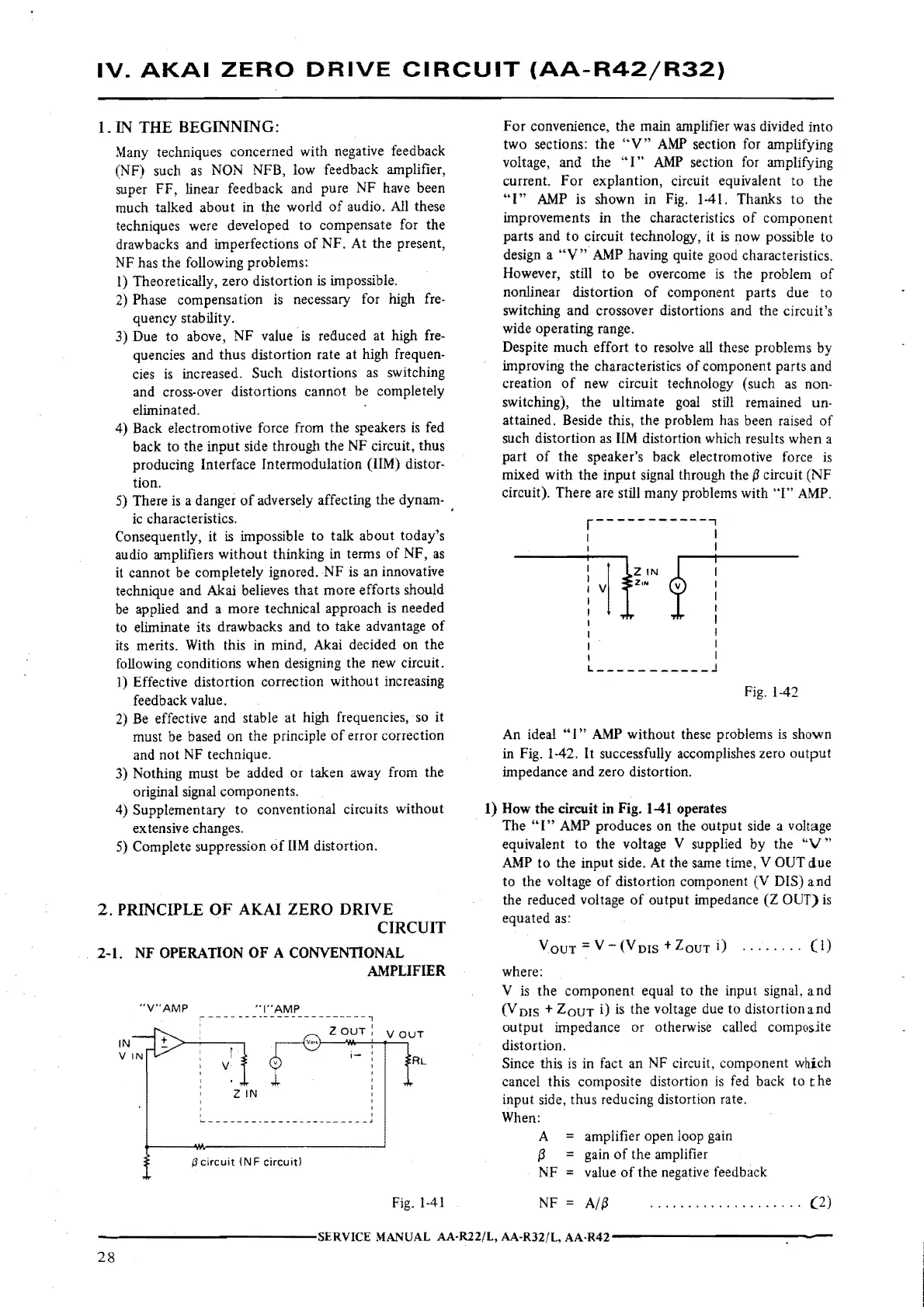
2-1.
NF
OPERATION
OF
A
CONVENTIONAL
AMPLIFIER
"V"AMP
''!"AMP
V
l
ZIN
'
--~---------------J
Ii
circuit
{NF
circuit)
V
OUT
AL
Fig. l-41
For
convenience,
the
main amplifier was divided
into
two
sections:
the
"V"
AMP
section for amplifying
voltage, and
the
"I"
AMP
section for amplifying
current.
For
explantion, circuit equivalent
to
the
"I"
AMP
is shown in Fig. 1-41. Thanks
to
the
improvements
in
the
characteristics
of
component
parts and
to
circuit technology, it
is
now possible to
design a
"V"
AMP having quite good characteristics.
However, still
to
be overcome
is
the problem
of
nonlinear distortion
of
component parts due
to
switching and crossover distortions and
the
circuit's
wide operating range.
Despite
much
effort
to
resolve all these problems by
improving
the
characteristics
of
component parts and
creation
of
new circuit technology (such as non-
switching),
the
ultimate goal still remained un-
attained. Beside this,
the
problem has been raised
of
such
distortion
as UM distortion which results
when
a
part
of
the
speaker's back electromotive force
is
mixed
with
the
input
signal through the
11
circuit (NF
circuit). There are still many problems with
"I"
AMP.
r-----------7
I I
I I
7TII:•r--
1
I
I I
L
___________
j
Fig. 1-42
An ideal
"I"
AMP
without
these problems is shown
in Fig. 1-42.
It successfully accomplishes zero
output
impedance and zero distortion.
1)
How
the circuit
in
Fig.
1-41
operates
The
"I"
AMP
produces on the
output
side a voltage
equivalent
to
the
voltage V supplied by
the
"V"
AMP
to
the
input
side. At the same time, V OUT
due
to
the voltage
of
distortion component (V DIS)
and
the reduced voltage
of
output
impedance
(Z
OUT)
is
equated as:
YouT
= V
(Vms
+ZoUT
i)
........
(l}
where:
V is
the
component
equal
to
the input signal,
and
(V
01s
+
ZouT
i)
is
the
voltage due
to
distortion
and
output
impedance
or
otherwise called composite
distortion.
Since this
is
in fact an NF circuit, component wnich
cancel this composite distortion
is
fed back to
the
input side,
thus
reducing distortion rate.
When:
A =
{3
NF
amplifier open loop gain
gain
of
the amplifier
value
of
the
negative feedback
NF
=
A/11
(2)
-------------SERVICE
MANUAL
AA-R22/L, AA·R32/L,
AA-R42-------------
28

 Loading...