Vis
then expressed as:
V
=
{3V
in+
N;~
1
CV
ms+
ZouT
i)
From
(I)
and (3), final
output
is given
as:
(3)
VouT
=
{3V
in+
N/+
I (VOis +
ZouT
i)
...
(4)
From
(4), the input signal is magnified
{3
times for a
conventional amplifier and distortion and
output
impedance becomes 1/(NF +
I).
2·2.
ABSORPTION
OF
SPEAKERS
BACK
ELEC·
TROMOTIVE
FORCE
IN
A
CONVENTIONAL
AMPLIFIER
(For
simplification, Vms was omitted.)
"V"AMP
.-.----
'
'
I
:
ZIN
I
I
L
___
_
------,
I
Z
OUT
I
I
I
I
I
I
•
I
I
I
I
"I"
AMP 1
_
___________
.,
Fig. 1-43
Fig.
1-43
shows a circuit equivalent
to
a speaker
which produces back electromotive force with
RL
and back electromotive force VR in a series circuit.
At
this time, the amplifier produces inverted phase
voltage through the NF circuit
to
absorb the
VR
but
not
completely. The residual voltage is:
VR
ZouT I
VouT = NF •
NF
+ 1
R
+NF+
I
ZouT
YR
ZouT
R
+ZouT
I
)
..........
(5)
This voltage
is
fed back
to
the previous amp stage
through the
{3
circuit, magnified
"-NF"
times,
VR
ZouT
NF
V'
=
NF
R
+NF+
1
ZouT
.
VR
Zour
(;::-
R+ZouT)
..................
(
6
)
and input
to
the
"I"
AMP.
The point that should be noted here
is
that,
as
can be
seen in ( 5), complete absorption cannot be obtained.
The residual voltage mixes with the input signal
through
the
{3
circuit, resulting
in
IIM
distortion.
Thus the drawback
of
conventional amplifiers can be
readily seen.
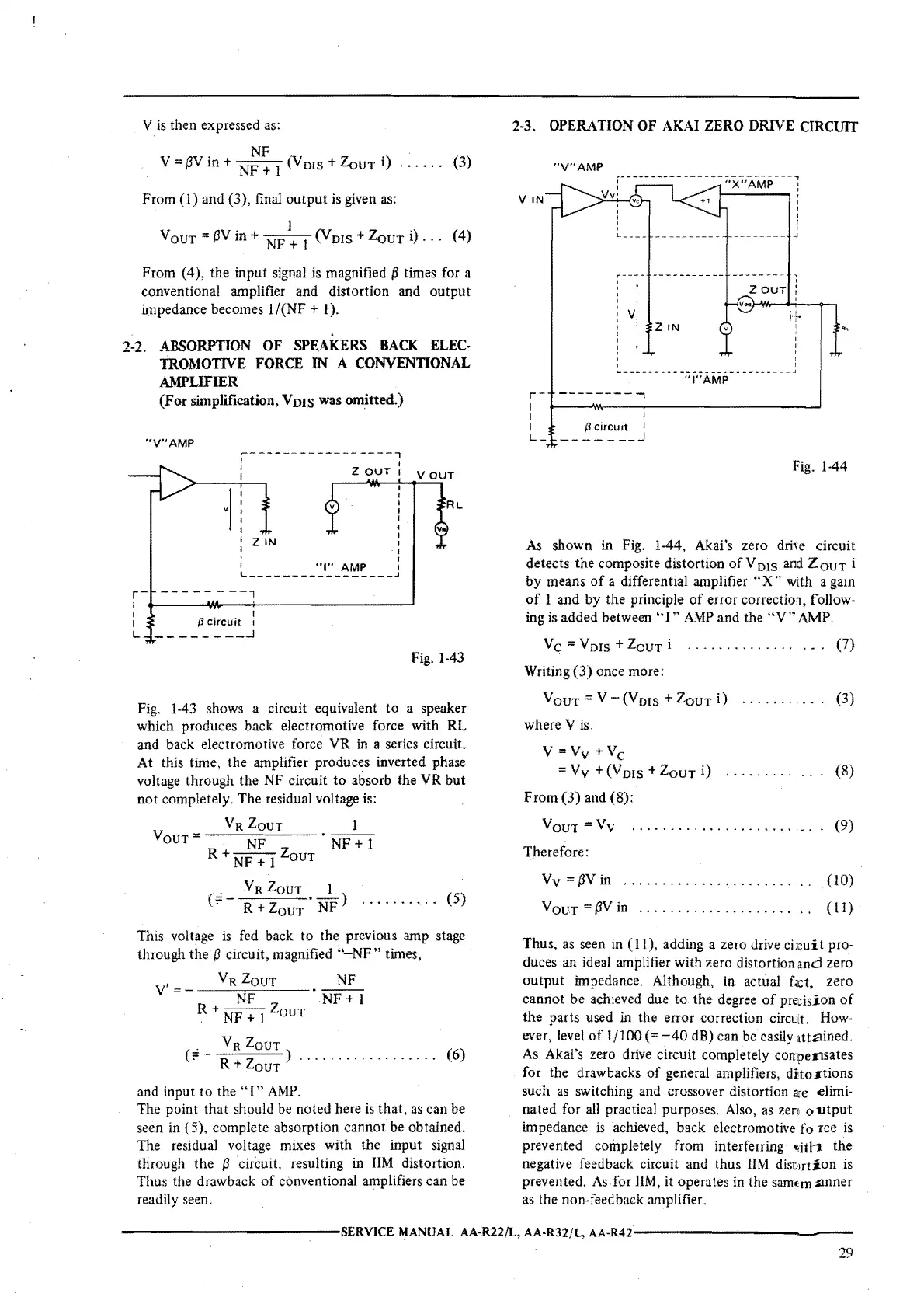
2-3.
OPERATION
OF
AKAi
ZERO
DRIVE
CIRCUIT
"V"AMP
VIN
r-
---------,
I
I
I
L -
I
{Jcircuit
1
----
-
__
.J
"X"AMP
!
"l"AMP
'
J
'
2
OUT
:
Fig.
1-44
As
shown in Fig. 1-44, Akai's zero dri,e circuit
detects the composite distortion
of
V DIS
and
ZouT
i
by
means
of
a differential amplifier
"X
•·
with a gain
of
I and by the principle
of
error correctioil, follow-
ing
is
added between
"I"
AMP
and the
"V"
AMP.
Ve=
Vms
+
ZouT
i
..................
(7)
Writing (3) once more:
VoUT=V-(Vms+ZouTi)
..........
(3)
where
Vis:
V
=Vv
+Ve
=Vv+(VDis+ZouTi)
.............
(8)
From
(3) and (8):
VouT
=Vv
Therefore:
. . . . . . . . . . . . . . . . . . . . . . . . . (9)
Vv
=
t3V
in
VouT
={3V
in
...................
.
(10)
( l
I)
·
Thus,
as
seen in (
11
), adding a zero drive
ci
;cu
it
pro-
duces an ideal amplifier with zero distortion
and
zero
output
impedance. Although,
in
actual
fact,
zero
cannot be achieved due to
the
degree
of
precision
of
the
parts used in the error correction
circU:t.
How-
ever, level
of
1/100
(=-40
dB) can be easily 1tt.ained.
As
Akai's zero drive circuit completely compensates
for the drawbacks
of
general amplifiers, dito..-tions
such
as
switching and crossover distortion
a-e
elimi-
nated for
all
practical purposes. Also,
as
zen 01.1tput
impedance
is
achieved, back electromotive
force
is
prevented completely from interferring
"itl:1
the
negative feedback circuit and thus
UM
distirtion
is
prevented.
As
for
JIM,
it operates
in
the sam,m :anner
as
the non-feedback amplifier.
------------SERVICE
MANUAL AA·R22/L, AA-R32/L,
AA-R42------------
29

 Loading...