PLL data value
is
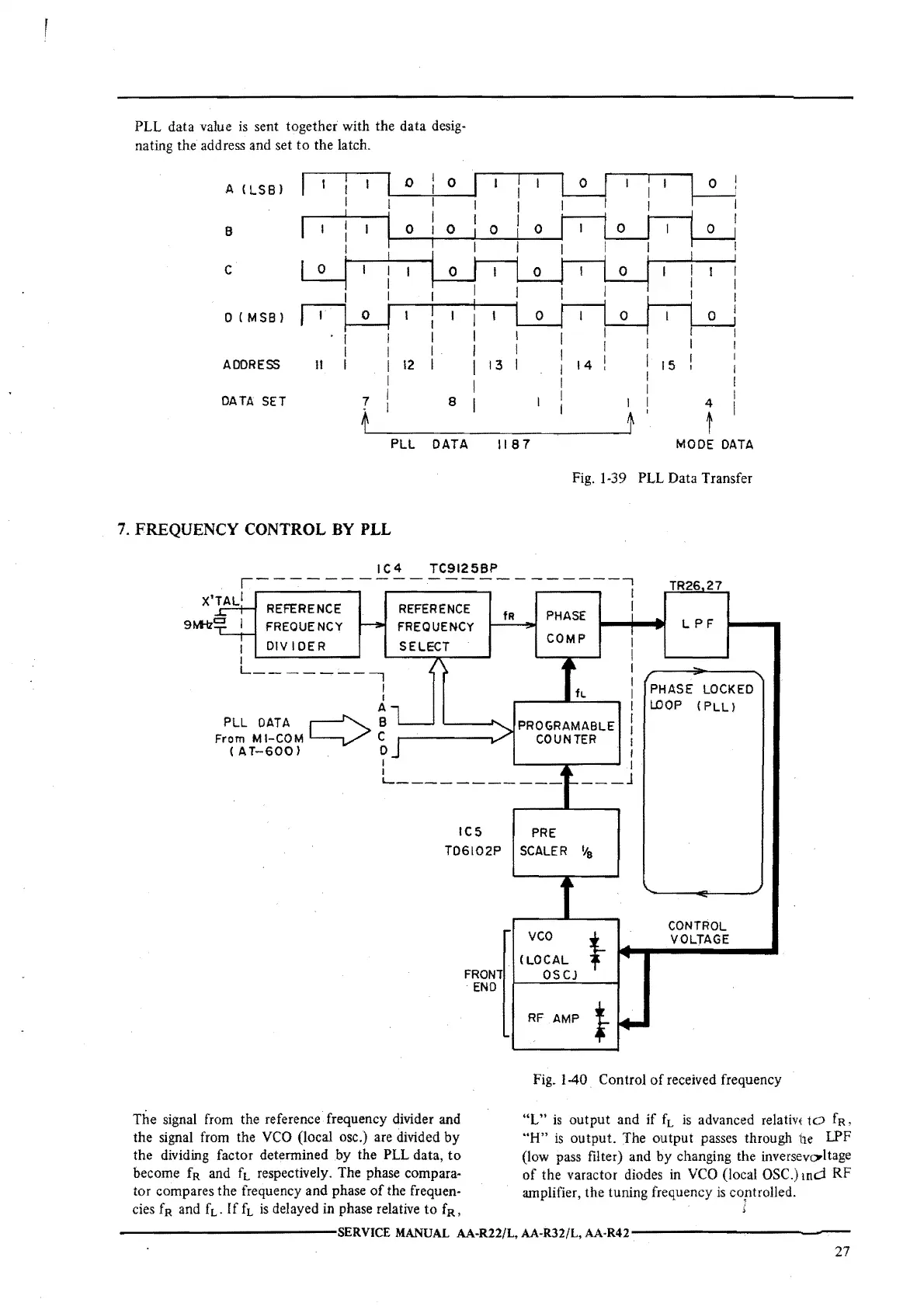
sent together with the data desig-
nating the address and set
to
the latch.
A
(LSBI
0 0
L:.J
~
I
I
B
0
0 0
0
!
C
0 (
MSB
I
ADDRESS
II
12
13
14
15
DATA SET
7
8
4
t
PLL
DATA
1187
MODE
DATA
Fig. 1-39
PLL
Data Transfer
7. FREQUENCY
CONTROL
BY
PLL
IC4
TC91258P
,------------------
TR26
27
X'TAL1
...-----,
REFERENCE REFERENCE
FREQUENCY
I
DIVIDER
I
L--
7
I
I
A
PLL
OAT
A
~
B
From
MI-COM
'--i,/
C
(
AT-600)
D
I
I
FREQUENCY
SELECT
fR
PHASE
COMP
I
I
I
I
I
I
PROGRAMABLE l
COUNTER I
I
I
L
PF
F
PHASE LOCKED
LOOP
(
PLL)
L-----
----
---
_J
IC5
T06102P
The signal from the reference frequency divider and
the signal from the
VCO
(local osc.) are divided
by
the dividing factor determined by the
PLL
data,
to
become
fR
and
ft
respectively. The phase compara-
tor compares the frequency and phase
of
the frequen-
cies
fR
and
ft.
If
ft
is
delayed in phase relative to fR,
FRONT
END
PRE
SCALER
'la
'
CONTROL
vco
t
VOLTAGE
(LOCAL
OSCJ
RF
AMP
}
Fig. 1-40 Control
of
received frequency
"L"
is
output and if
fL
is
advanced relativ(
to
fR,
"H"
is
output. The output passes through
i1e
LPF
(low pass filter) and
by changing the inversevc,,ltage
of
the varactor diodes
in
VCO
(local OSC.)
md
RF
amplifier, the tuning frequency
is
coptrolled.
------------SERVICE
MANUAL AA-R22/L, AA-R32/L,
AA-R42--------------
27
 Loading...