I.
OUTLINE
OF
AA-R
SERIES
SYSTEM
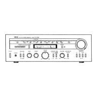
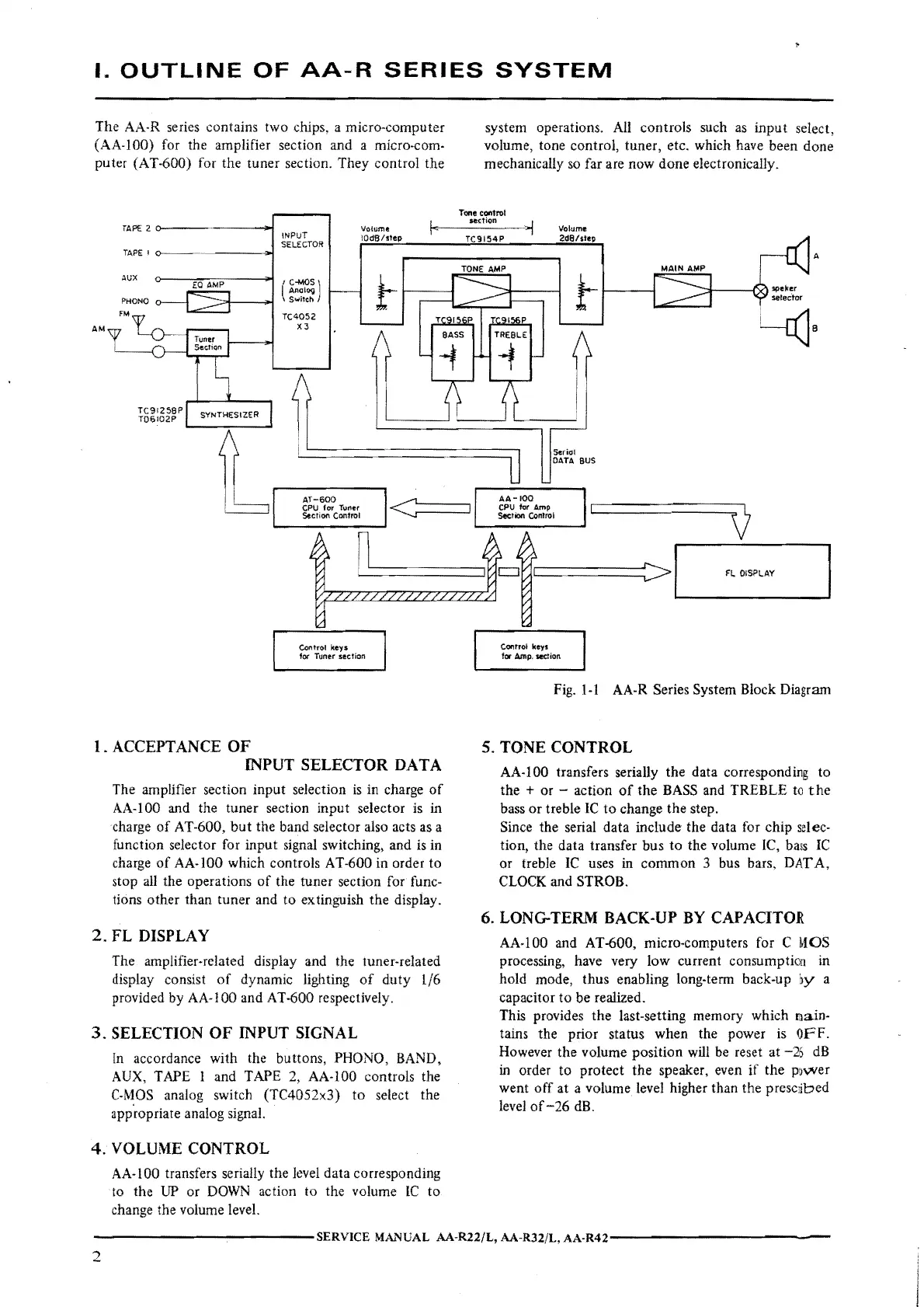
The AA-R series contains two chips, a micro-computer
(AA-100) for the amplifier section and a micro-com-
puter (AT-600) for the tuner section. They control the
AM
TAP!::
2
TAPE
I
AUX
PHONO
TC91256P
T06l02P
SYNTHESIZER
I·
Volume
INPUT
IOdS/step
SELECTOR
( C-MOS)
t
Analog
Switch
TC4052
X3
system operations. All controls such
as
input select,
volume, tone control, tuner, etc. which have been done
mechanically
so
far are now done electronically.
Tone
control
section
, I
TC9154P
Volume
2d0/step
t-
Serio!
DATA
BUS
A
speker
setector
l
----
AT-600
<:====:i
CPU
for
Tuner
Section Control
AA-100
CPU
for
Amp
Section
COnltOI
0
n
Control keys
for Tuner section
1.
ACCEPTANCE
OF
INPUT
SELECTOR
DATA
The amplifier section input selection
is
in charge
of
AA-100 and the tuner section input selector
is
in
charge
of
AT-600,
but
the band selector also acts as a
function selector for input signal switching, and is in
charge
of
AA-100 which controls AT-600 in order to
stop
all
the operations
of
the tuner section for func-
tions other than tuner and
to
extinguish the display.
2.
FL
DISPLAY
The amplifier-related display and the tuner-related
display consist
of
dynamic lighting
of
duty 1/6
provided by AA-100 and AT-600 respectively.
3.
SELECTION
OF
INPUT
SIGNAL
In
accordance with the buttons, PHONO, BAND,
AUX,
TAPE I and TAPE 2, AA-100 controls the
C-MOS
analog switch (TC4052x3)
to
select the
app.ropriate analog signal.
4.
VOLUME
CONTROL
AA-100 transfers serially the level data corresponding
to the
UP
or
DOWN
action to the volume
lC
to
change the volume level.
A'-,-
--------------------
--~---':>
l,_
___
F_L_◊_IS-Pl-AY
___
_,
Cootrot keyt
for
Amp,
section
Fig.
1-1
AA-R
Series System Block Diagram
5.
TONE
CONTROL
AA-100 transfers serially the data corresponding to
the
+ or - action
of
the
BASS
and TREBLE
to
the
bass
or
treble
IC
to
change the step.
Since the serial data include the data for chip
selec-
tion, the data transfer bus
to
the volume
IC,
bass
IC
or treble
IC
uses in common 3 bus bars, DAT A,
CLOCK
and STROB.
6.
LONG-TERM
BACK-UP
BY
CAPACITO.R
AA-100 and AT-600, micro-computers for C
MOS
processing, have very low current consumption in
hold mode, thus enabling long-term back-up
:iy
a
capacitor to be realized.
This provides the last-setting memory which
main-
tains the prior status when the power
is
OFF.
However the volume position
will
be
reset at -26
dB
in
order to protect the speaker, even if the power
went
off
at a volume level higher than the prescdbed
level
of-26
dB.
-------------SERVICE
MANUAL
AA-R22/L, AA-R32/L,
AA-R42-------------
2
 Loading...