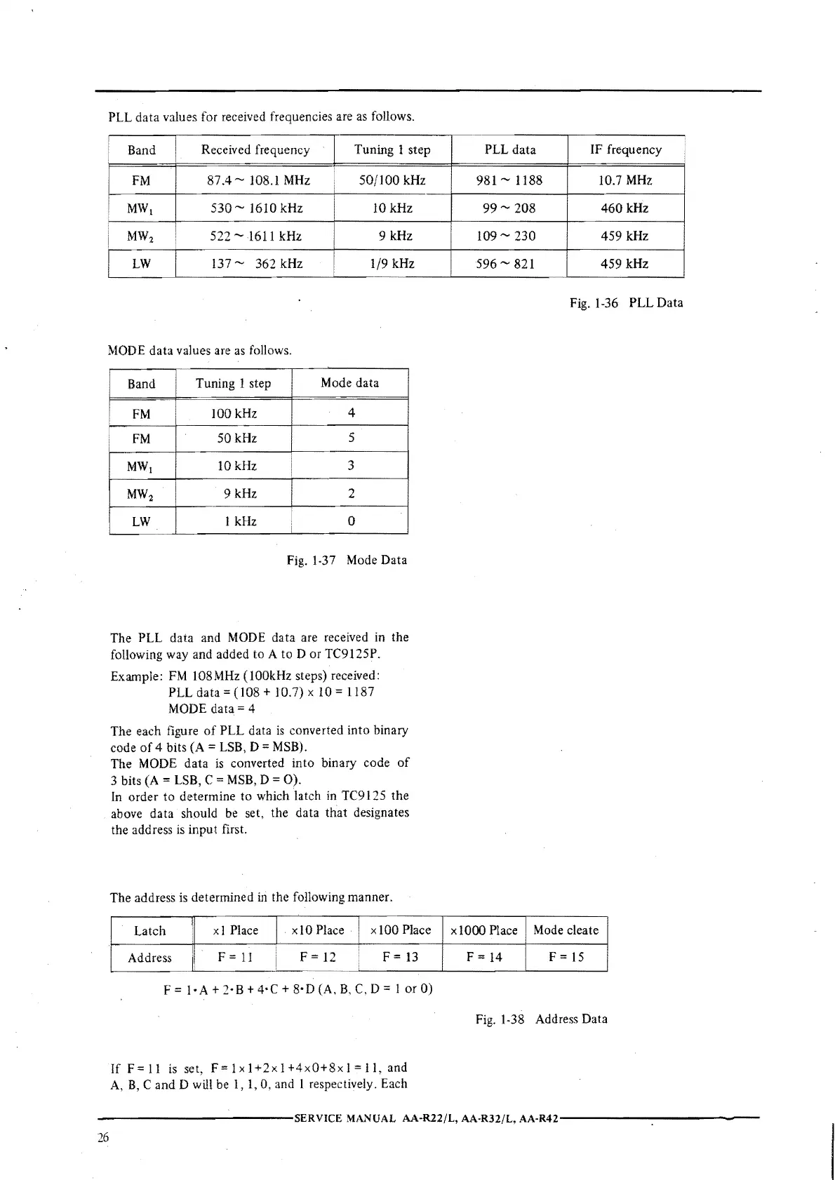
PLL data values for received frequencies are
as
follows.
!
Received frequency
Band
Tuning l step
FM
87.4~
108.1
MHz
50/100
kHz
MW
1
530
~ 1610 kHz
IO
kHz
MW
2
522 ~ 1611 kHz
9 kHz
LW
137 ~ 362 kHz
1/9 kHz
MODE
data values are
as
follows.
Band
Tuning 1 step
Mode data
FM
100 kHz
4
FM
50kHz
5
MW
1
lOkHz
3
MW
2
9 kHz 2
LW
I kHz
0
Fig. 1-37 Mode Data
The PLL data and
MODE
data are received
in
the
following way and added to A to
Dor
TC9125P.
Example:
FM
108MHz
(I00kHz
steps) received:
PLL
data=
(108 + 10.7) x
IO
1187
MODE
data=
4
The each figure
of
PLL data
is
converted into binary
code
of
4 bits (A = LSB, D =
.MSB).
The MODE data
is
converted into binary code
of
3 bits
(A
= LSB, C = MSB, D =
0).
In
order
to
determine to which latch
in
TC9 l 25 the
above data should
be
set, the data that designates
the address
is
input first.
The address
is
determined
in
the following manner.
Latch
:1
x I Place
I
xl0
Place
I
x 100 Place
Address
ii
F =
11
i
F = 12
F
=
13
F
I·
A+
2· B +
4·C
+ 8· D (A,
B,
C,
D = I or
0)
If
F=ll
is
set,
F=lxl+2xl+4x0+8xl=ll,
and
A,
B,
C and D will be 1, 1, 0, and I respectively. Each
PLL
data
IF frequency
981~
1188
10.7
MHz
99
~
208
460
kHz
109
~ 230
459 kHz
596
~ 821
459 kHz
Fig. 1-36 PLL Data
xl0OO Place
Mode cleate
F
=
14
F =
15
Fig. 1-38 Address Data
------------SERVICE
MANUAL
AA·R22/L,
AA-R32/L,
AA·R42------------
26
 Loading...