•
SAFETY INSTRUCTIONS
PRECAUTIONS
DURING
SERVING
1.
Parts identified by the
(*)
symbol
parts
are
critical
for
safety. Replace only
with
parts
number
specified.
2.
In addition to safety,
ether
parts
and assemblies are
specified
for conformance
with
such regulations as
these
applying te spurious radiatien.
These must also be replaced only
with
specified re-
placements.
Examples:
RF
cenverters,
tuner
units,
antenna
selec-
ter switches, RF cables, neise blocking capacitors,
neise blocking
filters,
etc.
3.
Use specified internal
wiring.
Note
especially:
1)
Wires covered
with
PVC
tubing
2)
Doublé
insulated wires
3)
High
voltage leads
4.
Use specified insulating materials for hazardous hve
parts.
Note
especially:
1)
Insulatien Tape
2) PVC
tubing
3)
Spacers (Insulating
Barriers)
4)
Insulatien
sheets
for transistors
5)
Plastic screws for
fixing
microswitch (especially
in
turntable)
5.
When replacing
AC
primary side
components
(trans-
formers, power cerds, noise blocking capacitors,
etc),
wrap
ends
of
wires
securely
about
the terminals
before
soldering.
7.
Check
that
replaced
wires
de not contact sharp
edged
er pointed parts.
8.
Also
check areas surrounding repaired lecatiens.
9. Use care
that
foreign ebjects (screws, selder dre-
plets, etc.) de net remain inside the set.
SAFETY CHECK AFTER SERVICING
Confirm
the specified insulatien resistance between
power cord plug
prongs
and externally exposed
parts
of
the set
is
greater
than 10 M ohms, but fer
equipment
with
external
antenna
terminals (tuner, receiver, etc.) and is
intended for ö er
[Al,
specified insulatien resistance
should be
headphone
jacks line-in-eut jacks etc. mere
than 2.2 M ohms (ground terminals, microphone
jacks).
6.
Observe
that
wires do net contact
heat
producing
parts
(heatsinks, oxide metal
film
resistors, fusible
resistors, etc).
•
INFORMATION
SYMBOLS
FOR
PRIMARY
DESTINA-
TION
Alphabet indicates the destination of the units as listed
below.
Symbols
Principal
Destinations
USA
m
UK
Canada
Europe (except
UK)
m
Japan
Australia
m
W.
Germany only
Universal
Area
Custom version
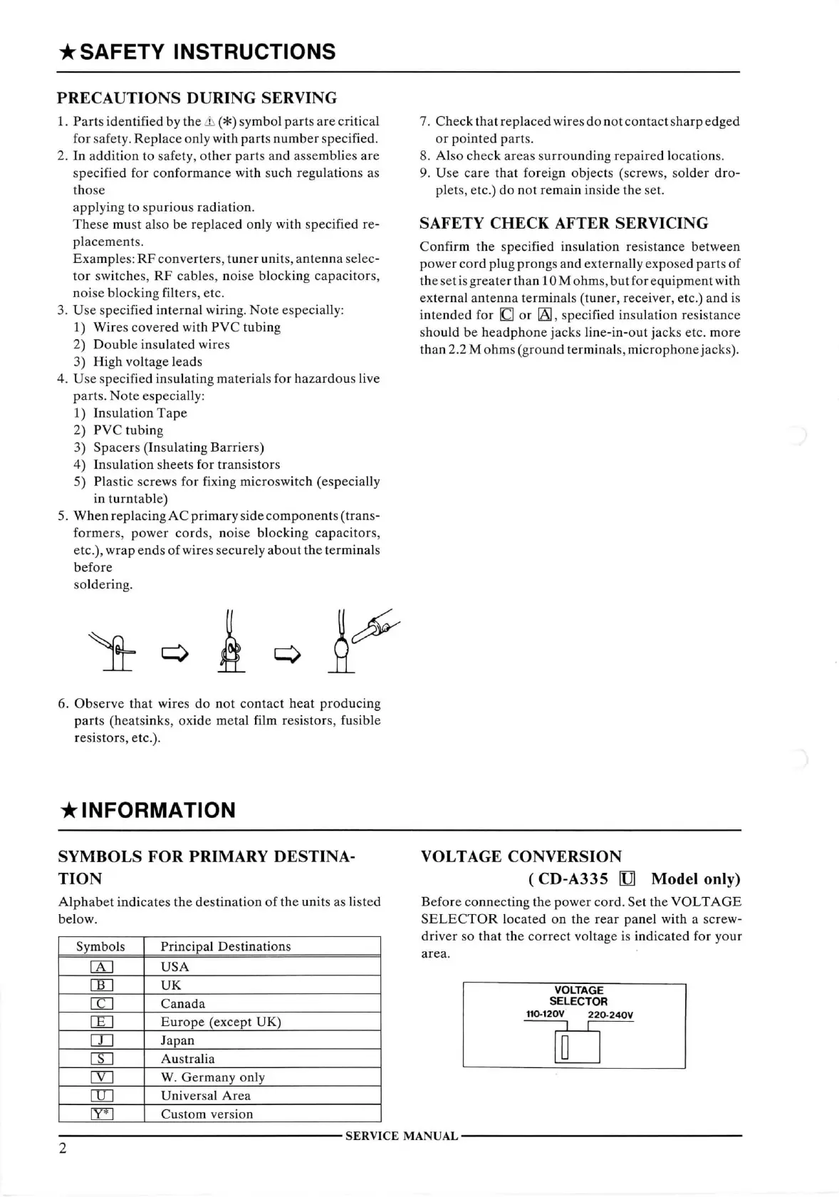
VOLTAGE
CONVERSION
(CD-A335
O Model only)
Before
connecting the power cord. Set the
VOLTAGE
SELECTOR
located en the rear panel
with
a screw-
driver
se
that
the correct voltage is indicated for yeur
area.
VOLTAGE
SELECTOR
110-120V 220-240V
n
r—
2
SERVICE
MANUAL
 Loading...