This document outlines the specifications, operation, and maintenance of the AKAI CD-57 Compact Disc Player.
Function Description
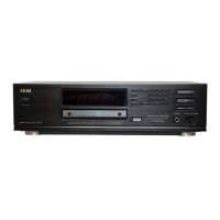
The AKAI CD-57 is a compact disc player designed for high-fidelity audio playback. It utilizes a 3-beam laser pick-up system for accurate disc reading and incorporates an 18-bit, 8-times oversampling digital filter with an interpolative one-bit dual D/A converter for precise digital-to-analog conversion. The player includes a cross interleave reed solomon error correction system to ensure reliable playback. It supports 2-channel stereo output and offers both fixed and variable analog outputs, as well as coaxial and optical digital outputs. A headphone output is also provided for private listening. The unit features a front panel with controls for power, disc tray operation, and playback functions, along with a display for track and time information.
Important Technical Specifications
Pick-up system: 3 beam laser pick-up
Sampling frequency: 44.1 kHz
Digital filter: 18 bit, 8 times over sampling
D/A converter: Interpolative one bit dual
Error correction system: Cross interleave reed solomon
Number of channels: 2 channel stereo
Frequency response: 2 Hz to 20 kHz ± 0.5 dB
Dynamic range: 97 dB (1 kHz)
S/N ratio: 108 dB
Total harmonic distortion: 0.0028% (1 kHz)
Wow & flutter: Less than measurable limits
Output level / Impedance:
- Analog output (Fixed): 2 V / 330 ohms
- Analog output (Variable): 2 V / 330 ohms
- Digital output (Coaxial): 0.5 Vp-p / 75 ohms
- Digital output (Optical): -22 dBs
- Headphone output: 32 mW / 32 ohms
Power requirements:
- 220 V-230 V, 50 Hz for Europe except UK
- 240 V, 50 Hz for UK and Australia
Dimensions: 425 (W) X 120 (H) X 349 (D)mm
Weight: 4.6 kg
Standard accessories:
- Connection cord (X1)
- Remote control unit (RC-C57) (X1)
- Batteries for the remote control unit (X2)
- Operator's manual (X1)
Usage Features
The CD-57 offers a user-friendly interface with essential controls on the front panel. It includes a "TEST mode" for adjustment and checking, which can be accessed by pressing the "II" and "buttons simultaneously during power-on. Within the TEST mode, users can navigate through different modes using the "button to adjust various parameters such as tracking servo gain, focus offset, and focus servo gain. The display provides feedback on the current test mode, track information, and search status. The unit supports normal play mode with anti-shock functionality, which can be toggled on or off. The inclusion of fixed and variable analog outputs, along with digital outputs, provides flexibility for connecting to various audio systems. A remote control unit (RC-C57) is included for convenient operation.
Maintenance Features
The service manual provides detailed instructions for disassembly and replacement of principal components.
Disassembly:
- Upper Cover: Remove screws to detach the upper cover.
- Front Panel: Remove screws to detach the front panel.
Replacement of Principal Components:
- General Precaution: When removing motors (spindle, loading, sled) or the pick-up block, the mecha block and disc clamper must be removed first.
- Laser Diode Protection: To prevent damage to the laser diode (LD) during mecha block removal, short the short points on the pick-up block's PCB with solder before removing the MAIN PCB's P2 or P3 connectors. When installing a new pick-up block or mecha block, connect P2 and P3 first, then remove the solder from the short points.
- Disc Clamper Removal: Move the disc drawer forward by turning the loading gear counterclockwise, remove the disc clamper spring, then lift and move the disc clamper to the left.
- Mecha Block Removal: Remove retaining screws, turn the mecha block over, short the pick-up block's short points with solder, and then remove P2, P3, P5, and P6 connectors from the MAIN PCB.
- Spindle Motor Removal: Move the pick-up block by turning the sled motor counterclockwise, remove spindle motor retaining screws, then move and remove the spindle motor.
- Loading Motor Removal: Remove the loading belt, turn the mecha block over, open the loading motor's 3 retaining hooks, and remove the motor.
- Pick-up Block Removal: While moving the stopper to the right, press the top part of the pick-up sled shaft to extract it, then remove the pick-up block.
Electrical Adjustment:
The TEST mode allows for precise adjustments:
- E-F Balance: Use Test disc 5A (AT-751330) in Test mode 3. Connect an oscilloscope to TP 3 (TE) and adjust VR 2.
- VCO: After 10 seconds of power-on, connect a frequency counter to TP5 (WFCK) and adjust VR 5 to 7,350 ± 50 Hz. A jumper wire between TP 1 (EFM) and TP 2 (GND) is required.
- Tracking Servo Gain: Use Test disc 5A (AT-751330) in PLAY mode. Connect an oscilloscope to pin ⑥ (TRK) of connector P2 and adjust VR 3 for 0.8 to 1.2 Vp-p.
- Focus Servo Gain: Use Test disc 5A (AT-751330) in PLAY mode. Connect an oscilloscope to pin ⑧ (FCS) of connector P2 and adjust VR 4 for 1.0 to 1.4 Vp-p.
- Focus Offset: Use Test disc 5A (AT-751330) in Test mode 2 and 1. Connect a digital DC voltmeter to TP 4 (FE). Check voltage A in Test mode 2, press STOP, and adjust VR 1 so that the voltmeter reading matches voltage A.
Safety Instructions:
- Critical Parts: Parts identified with ▲ (*) symbol are critical for safety and must be replaced only with specified part numbers.
- Spurious Radiation: Other parts and assemblies specified for conformance with spurious radiation regulations must also be replaced only with specified replacements.
- Wiring and Insulation: Use specified internal wiring (PVC tubing, double insulated, high voltage leads) and insulating materials (insulation tape, PVC tubing, spacers, insulation sheets for transistors, plastic screws).
- Soldering: When replacing AC primary side components, wrap wire ends securely about terminals before soldering.
- Heat and Sharp Edges: Ensure wires do not contact heat-producing parts or sharp edges.
- Foreign Objects: Prevent foreign objects (screws, solder droplets) from remaining inside the unit.
- Laser Safety: This product contains a Class 1 laser device. Do not remove covers or attempt to access the inside. Refer servicing to qualified personnel. Do not watch the laser beam directly. Laser warning labels are affixed to the unit and inside.
- Static Electricity: Micro-Computer and CD signal processing ICs can be damaged by static electricity or leakage from a soldering iron. Take precautions during soldering.
- Mechanical Parts: Do not apply excessive pressure to mechanical parts, including the pick-up block, due to high precision requirements.
- Metal Objects: When the base is removed, ensure no metal objects are in the narrow gap between the P.C. board and mecha parts.
- Pick-up Block Screws: Do not loosen any screws in the pick-up block.
Environmental Protection:
Used batteries with the ISO recycling symbol, as well as small accumulators, mini-batteries, and starter batteries, should be disposed of at an appropriate depot, not in household garbage. Other household batteries can be discarded with household waste.