II. DISASSEMBLY
In
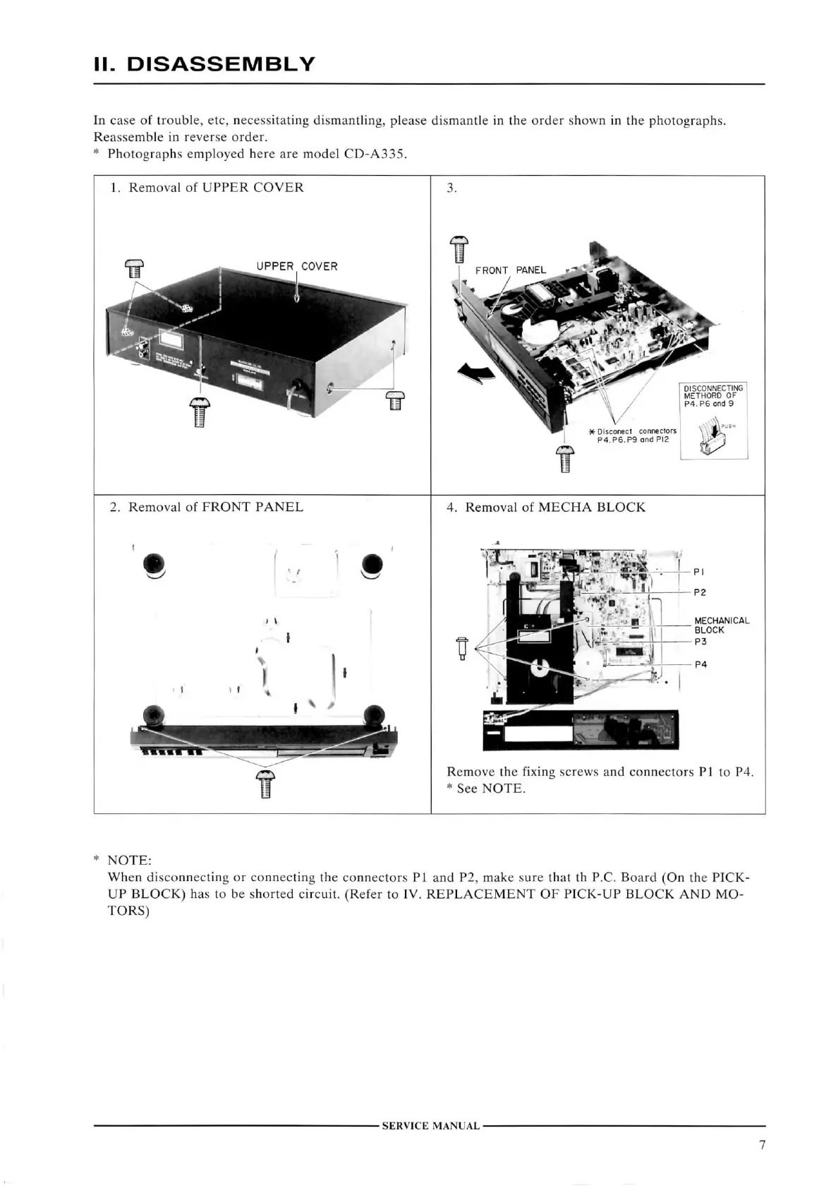
case of troiible, etc, nece.ssitating dismantling, please dismantle in the order shown in the photographs.
Reassemble
in reverse order.
*
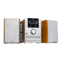
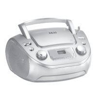
Photographs employed here are model
CD-A335.
1.
Removal
of
UPPER COVER
UPPER
COVER
2.
Removal
of
FRONT PANEL
V
.
4.
Removal
of
MECHA BLOCK
PI
P2
MECHANICAL
BLOCK
P3
Remove
the
fixing
screws and connectors PI to P4.
*
See
NOTE.
NOTE:
When
disconnecting or connecting the connectors PI and P2, make sure that th
P.C.
Board
(On the
PICK-
UP BLOCK)
has to be shorted
circuit.
(Refer
to
IV. REPLACEMENT
OF
PICK-UP BLOCK
AND MO-
TORS)
SERVICE
MANUAL
7