S.
IC3 (HA12020) REFERENCE VOLTAGE
ADJUSTMENT (Fig. 12)
a.
Set
the mode to REF. ( with power
ON,
REF is
achieved)
b. Adjust VR2 (L) so that the voltage to
GND
of
TPl will
be
1.10 ± 0.03V
DC.
c.
Adjust VR2b (R) so that the voltage to
GND
of
TP2
will
be
4.00 ± 0.05V
DC
(before SERIAL
NUMBER
70401-00101), 5.10 ± 0.05V
DC
(after
SERIAL NUMBER 70401-00101}.
6. REC BIAS OSC ADJUSTMENT (Fig. 12)
a.
Set
a metal tape and set to REC/PLAY mode.
b.
Set
VCl
as
shown in Fig. 12.
c.
Connect the frequency counter to
PS
(tuning
PCB)
and
adjust
Tl
so
that the frequency will be 100 ±
0.2 kHz.
d.
Connect a
DC
voltmeter to both ends
of
R203
(I ohm) and adjust T2
so
that the voltage will be
at
minimum.
7. FREQUENCY RESPONSE
ADJUSTMENT (Fig.
12)
a.
Record and play back l kHz/10 kHz,
-25.5
dBm
using a normal tape and adjust
VC
1
so
that
1 kHz/IO kHz will be
O ± 0.5
dBm
(provided
L-R
difference
is
within 0.5 dBm).
b.
Record and play back 1 kHz/IO kHz,
-25.5
dBm
using a CrO
2
tape and adjust VR4
so
that
l kHz/10 kHz will be O ± 0.5 dBm.
c. Record and play back 1 kHz/IO kHz,
-25.5
dBm
using a metal tape and adjust VR3
so
that
I kHz/IO kHz
will
be O ± 0.5 dBm.
8.
RECORDING LEVEL ADJUSTMENT
(Fig. 12)
Record and play back I kHz,
-5.5
dBm using a
normal tape, and adjust
VRl
so that the difference
between recording and play back levels
will
be
O ± 0.3
dBm.
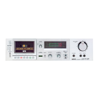
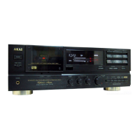
GX-F71
9. TEST SIGNAL ADJUSTMENT (Fig. 12)
a.
In REF mode, with recording volume to
MIN.
(or
input: OFF), connect
TP5
and TP8 to GND.
b.
Connecting
an
AC
voltmeter (mV meter) to TP4,
adjust VR6
so
that the
AC
voltmeter difference
when TP6 and TP7 are connected
to
GND and
when they are not connected, will be within
0.5 dBm.
Reference:
When both TP6 and TP7 are open .....
TEST SIGNAL: I kHz
When
TP6 = open, TP7 GND .....
TEST SIGNAL: 7 kHz
When
both TP6 and TP7 are to GND .....
TEST SIGNAL:
13
kHz
c.
With the monitor
SW
to SOURCE, adjust VRI
(Fig.
11
Pre Amp
PCB)
so that the LINE OUT
level will
be
-25.5
± 0.2 dBm.
10. LEVEL ADJUSTMENT OF PLAYBACK
OUTPUT LEVEL DETECTION CIRCUIT
Adjust
VRS
so
that the voltage to GND
of
TP3
will
be
4.0 ±
0.IV
DC
(before SERIAL NUMBER 70401-
00101),
5.1
±
0.lV
DC
(after SERIAL
NUMBER
70401-00101) under
9-C
conditions.
NOTES:
I.
Using
a digital voltmeter for the measurement
of
DC
voltage and an
AC
voltmeter (m V meter)
for
AC
voltage measurement, the input imped-
ance should
be
IOM
ohm or more.
2. Output level control should be at maximum.
3.
Use
the following cassette measuring tapes:
Normal tpae : Maxell
UD
C-60
CrO
2
tape TDK
SA
C-60
Metal tape :
TDK
MA
C-60
4-15
 Loading...